
Transforming Kites Into Wings
By Tim Bailiff [email protected]
Photos by Maggie Madrill and David Smith
As seen in the April 2025 issue of Model Aviation.
There are at least eight Rogallo-wing models in my RC squadron. The larger wings were built using fiberglass tubes and lightweight rip-stop nylon, just like commercial sport kites. All of my Rogallo wings have been scratch-built, original designs—until now!
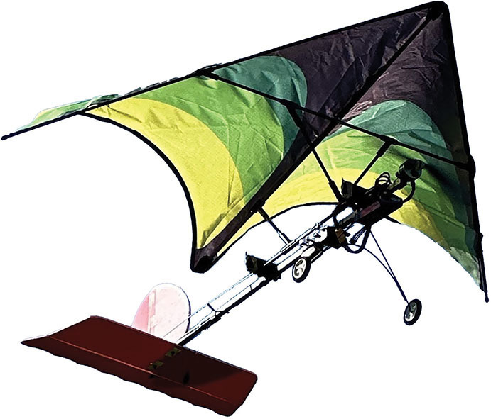
I will detail a quick, fun, "kite-plane" conversion using a particular sport kite known as a delta-wing. This kite is a type of Rogallo design! Instead of spending time measuring, cutting, and sewing rip-stop nylon, a premanufactured kite "covering" was utilized. Does this sound interesting?
Credit Where Credit Is Due
I recently visited a neighboring RC club in Hemet, California. There was a rumor floating around that the Diamond Valley Flyers had been substituting delta-wing kites for some of their wings. Although I have been flying similar homemade Rogallo designs for years and have considered using kites myself, they beat me to it. They had all sorts of interesting airplanes, including one that used a 9-foot kite! What a fun morning that was as I joined them in the air with one of my own designs. I credit those club members with the inspiration for the following fun kite-plane build.

An Offer I Couldn’t Refuse
Shortly after my visit, Ron Hudson, my own Valley Wide RC Electric Club’s president, approached me with a fun idea. He proposed that we collaborate on a joint kite-plane project. He had a GWS Slow Stick fuselage, including tail feathers, and an E-flite 480 motor. He had also purchased a green Mint’s Colorful Life 60-inch delta-wing kite on Amazon. We agreed that he would be responsible for the fuselage, etc., and I would handle the kite wing.
Multiple companies sell the same 60-inch delta-wing kite on Amazon, branded with their own logo. I know because I had such fun with Ron’s airplane that I decided to build one for myself. I purchased my kite from a different company and, other than the color, I found both kites to be the same.
My Own Spin on It
Although there are many ways to attach a kite to an airplane fuselage, this is my spin on it. In the past, I used fiberglass tubes and kite hardware on all of my rip-stop nylon designs. They were successful, so that’s the way I decided to roll. Because we would be using the kite as a Rogallo wing, the front, printed side would be the top of the wing. That meant we would actually fly the kite upside down! Interesting, right?

A Few Simple Modifications
Initially, we tried using the kite without modification. Early on, however, it became clear that it was not a very stable wing design. Although it would fly, we ran into trouble controlling it. Sometimes it would turn fine in one direction but then not at all in the other. On one occasion, a simple turn became unrecoverable. We could do little more than watch it slowly spiral, out of control, into the ground. Not good!
We cropped the wing, loosened the fabric, and increased our wing’s angle of attack (AOA). Like magic, the issues were resolved. Our kite-plane became stable, controllable, and a whole lot of fun to fly!
Let’s Do This
I recommend that you read this entire article before you start your project. You won’t find any plans, but I have included ample construction photos. The materials list is tailored to be used with a 60-inch delta-wing kite and GWS Slow Stick fuselage. With only a few changes, this list could easily be used with any number of kites and fuselages. Because I had them on hand, I used fiberglass tubes and older kite hardware. If you wish to substitute carbon-fiber tubes and newer kite hardware, it would be even better.
Begin Your Build
I suggest that you first cut all of your 5mm and 6mm fiberglass tubes to length ahead of time. Be sure to smooth and round off your cut rod ends by lightly sanding them. The long sections of two 5mm 45° connectors will need to be drilled out to fit 6mm fiberglass tube front struts. The two connectors’ shorter sections will ultimately attach to your kite-plane’s 5mm spar.
Test-fit all of your connectors onto their respective rods. They should be slightly snug but also reasonably manageable. If necessary, gently drill out any overly tight connectors.
Some Removal
It’s time to remove all of the kite’s existing fiberglass rods and rod fittings. They are too flimsy for this project. You can certainly save them for a future one.
On the front (printed) side of the kite covering, you will find a triangular fabric "bridle" where the kite string is normally attached. You won’t need it so using scissors, carefully trim it away. No need to trim too close. Turn the kite material over and cut off the two small white ribbons that would normally secure the covering to the center keel and spar.
Some Wing Modifications
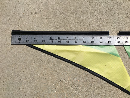
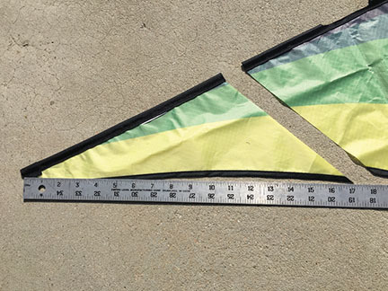
Start by laying the kite covering flat on your worktable, color side down. Measure forward one foot from the wingtip, along the sleeve’s leading edge (LE). From that point, lay a straightedge to the rear of the black, reinforced center keel pocket. Make sure that the fabric is as flat and smooth as possible. Using a new razor blade, make a single, clean cut along the straightedge.
Because of the sweep of the trailing edge (TE), this cut will take approximately 17 inches off of the wingtip. Do this to both wing halves. Be sure to reference the photos for clarity.
You will be inserting a 6mm fiberglass "keel" into the sleeve that is already sewn down the center of your wing; however, a few scissor cuts need to be made into the sleeve first. The first sleeve cut is just ahead of the rear black, reinforced pocket. Make the next sleeve cut 5-1/2 inches forward of your first cut, with another cut 2 inches forward of that one. Another cut is required 8-1/2 inches forward of the last cut, and one more is made 1/2 inch forward of that cut. One final sleeve cut needs to be made slightly behind the forward black, reinforced keel pocket. You still with me?
There is only one cut remaining. It requires slicing the rear black, reinforced keel pocket. You will need a razor blade to only cut through the top portion of the pocket crossways, halfway back. Be careful not to cut any of the stitching along the side. Check out the photos to help find the exact location.
A Custom V Connector
It’s time to make the custom V connector. For this, you will use three of the 6mm 45° connectors. I have provided a four-photo collage detailing the steps that are required to make it.
While preserving the longest parts of two connectors, cut and glue them together to form a 70° V. Medium CA glue, plus a light spray of CA kicker, will do the job. Now use six wraps of upholstery thread to hold the two pieces securely together at the bottom, and then soak the thread with thin CA. After the CA sets, notch the bottom of the V to create a saddle, as shown in the photos.
Next, cut a 2-1/4-inch tube from the third 45° connector piece. Rough up the middle of the tube slightly with sandpaper then secure the V’s saddle to the roughened middle of the tube by gluing and binding it with multiple wraps of upholstery thread that has been soaked with thin CA. Keep your wraps neat. Again, use the photos for clarity.

Time to Assemble
Starting at either wingtip, slide the 30-1/4 inch 5mm rod into the LE rod sleeve. You will note the two existing cutouts along the sleeve. Push the rod through and ignore the rear cutout. As the rod appears at the forward cutout, slide on a 5mm 45° connector. Note in the photos the direction that the connectors face. They will be used to connect the spar to both LEs. Press the 5mm caps onto both ends of the rod. Continue pushing the rod all the way forward while keeping the 45° connector positioned within the forward cutout. After the LE rod is in all the way, do the same to the other LE.
The Wing’s Keel
Starting from the rear cut, insert the 30-1/4-inch 6mm fiberglass keel tube into the center sleeve and push it forward. As you get to the next cut, allow the keel to exit the sleeve, and then slide on one of the 6mm 45° connectors so that it angles forward. While holding the connector in place, push the rod forward, reentering the sleeve. Continue holding the connector in place and push the rod forward to the next cut.
Allow the tube to exit that cut, but then immediately reenter the sleeve on the following cut. This will expose roughly 1/2 inch of the 6mm tube and is where it will later be secured to the spar. After pushing all the way forward and into the front black, reinforced holder, insert the rear of the keel into the slit that you cut in the rear black, reinforced pocket. It might be a bit of a struggle, but it’s doable.
Adding the Spar
Begin by marking the center of the 21-1/2-inch 5mm fiberglass spar. Slide the two previously drilled 5mm 45° connectors onto the spar. They should mirror each other with the long portions angled toward each other. Now slide the spar into both LE connectors. When your spar and LE connectors are positioned correctly, your spar will be 12 inches from the front of the wing. Your covering will be very loose and that’s exactly what you want. Note that your wingspan has now gone from 60 inches to 40 inches.
Center your spar over the 1/2-inch cut in the center sleeve where the keel is visible. Bind both the spar and keel together using multiple wraps of heavy Dacron fishing line (or similar). That completes the main structure of the wing.

Wing Saddle Structure
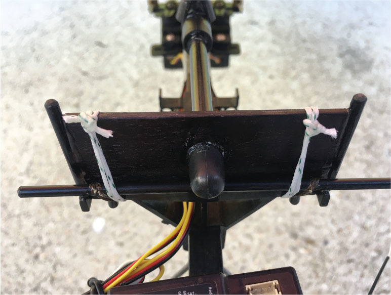
Begin with the two 3/32-inch plywood wing saddle adapter pieces. Both should be cut 2-1/2 × 1 inch tall with a 6mm hole drilled in the center. Sand them smooth. To the 1-inch sides of each, CA glue two 1-1/4-inch lengths of 3mm rod as keepers. Center them so that they protrude slightly on both the top and bottom to help keep the wing rubber bands, etc., in place. To keep things neat and color coordinated, I finished my plywood using a black Magic Marker.
Slide the 12-1/2-inch 6mm fiberglass tube through the hole in one of the plywood adapter pieces, allowing it to extend 1/4 inch beyond. This will be the front of the structure. Place a 6mm cap onto the protruding tube and glue the tube and cap to the plywood with CA glue. Slightly roughing the surface of the fiberglass tube with sandpaper helps the CA adhere better.
Slide one 6mm plastic sleeve onto the tube, push it up to the forward plywood adapter, and glue it in place. Now slide in the V connector and position it upright so that its center is 2-1/2 inches from the back of the forward plywood adapter.
Slide on a 6mm, 45° connector so that its center is 6 inches from the V connector’s center. The long portion of the 45° connector should be angled toward the rear. Do not glue any connectors yet.
Slide on a 6mm sleeve, the other plywood adapter, and a 6mm cap. Before you glue anything further, test-fit the entire saddle structure into your airplane’s wing saddle. The previously glued plywood adapter should be seated squarely in the forward wing saddle. Position the rear plywood adapter as necessary to fit squarely into the rear wing saddle.
Tack-glue the rear plywood adapter lightly to the 6mm rod. Ensure that you don’t get any CA on the wing saddle itself. Remove it when the CA has set and complete gluing the rear plywood adapter using the sleeve and cap as you did with the front plywood adapter.
Final Wing Assembly
You are almost done, so let’s get to it. Insert both 7-inch 6mm forward struts into the V connector. Be sure that they are both completely seated. Insert the 5-1/2-inch 6mm rear strut into the rear connector. Now place your kite wing upside down on a flat surface. Invert the wing saddle assembly and attach the 7-inch forward struts to the two connectors on the spar. You will need to slide the connectors onto the spar to match the position of the forward struts.
Using the center mark on your spar as a guide, make sure that both forward struts are aligned and spaced evenly. Now connect the rear strut to the connector that was previously attached to the rear of the keel. Make sure that all three struts are fully seated.
Flip the wing over, allowing the wing-saddle assembly to support it. Level the wing by measuring at the wingtips. Brace as necessary to maintain a square and aligned wing. Check the spacing on your spar and struts a final time then, without moving anything, use small amounts of thin CA to neatly glue the connectors to the struts. After the thin CA has wicked into the connectors, go back and use medium CA and kicker at the same locations.
I used several wraps of 1/4-inch blue painter’s tape to hold my spar connectors in place instead of CA glue. I did the same for my keel and LE connectors. After my first test flight, I added an additional wrap and decided to leave the tape. This allows you to remove the wing from the saddle assembly, should you wish to do so.
Go Fly a Kite
It’s time for your maiden flight! At the flying field, attach your wing with either four rubber bands or, as I did, the heavy Dacron fishing line used earlier. After your wing is secure, check for the proper balance. Your airplane’s center of gravity should be right on the spar.
After completing your preflight checklist, place your airplane on the runway facing into the wind. When you are cleared for takeoff, gradually apply full power. As your airplane accelerates down the runway, you will see your wing "inflate." With a touch of up-elevator, your model will gently lift into the air.
When it is airborne, allow your airplane to gradually gain altitude. When you reach a comfortable height, throttle back and trim for straight-and-level flight. Now try some gentle turns. You will find just how nice and stable your kite-plane flies. As you gain confidence, try a few more maneuvers, but before you try any aerobatics, I have a bit of advice.
Some Friendly Advice
Remember seeing your wing inflate? As built, your Rogallo kite-wing has a roughly 15° positive AOA. Therein lies the magic of this type of wing. The two "inflated," semiconical shapes formed by the wing’s fabric produce lift. A positive AOA must be maintained for your model to stay aloft. That means that if you wish to try some stunts, positive-G maneuvers, such as inside loops and wingovers, are the name of the game.
When It’s Time to Land
Kite-wings tend to produce a significant amount of drag. Chopping the throttle completely will result in a steep landing approach. This can be a fun way to land if you are expecting it. If, however, you are on an extended final and find that you are a little low, simply add a little throttle to help carry you in. When the aircraft is a foot above the runway, cut the power, flair, and you will make a beautiful three-point landing. As long as you take off and land into the wind, your new wing can handle a fair amount of it. After all, it was once a kite.
In the Pilots’ Lounge
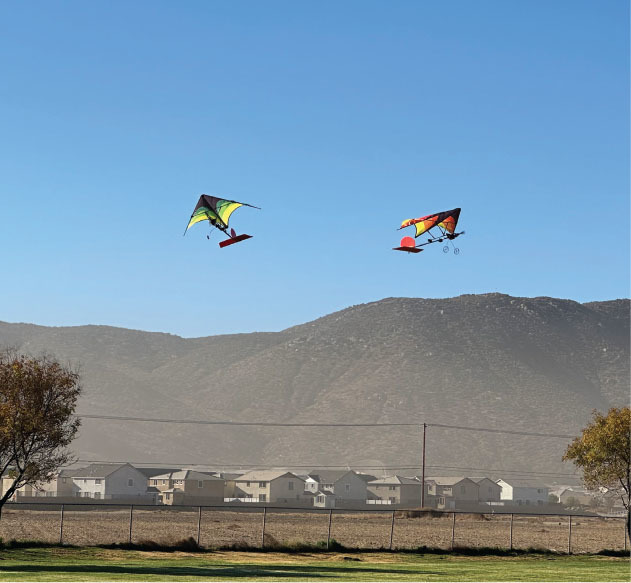
I hope you enjoy building and flying your kite-plane. After a short time in the air, I know that you will find it super relaxing and great fun to fly. Encourage your fellow pilots to build one as well.
As you can see in the aerial photos, the only things more eye-catching than an airborne kite-plane are multiple soaring kite-planes.
So, until next time, I wish you many fun and memorable flying adventures. Remember, stay safe, stay well, and stay positive—roughly 15°. Fun stuff …

Material and Parts List
6mm fiberglass tubes:
- One 30-1/4-inch center keel
- One 12-1/2-inch wing saddle rod
- Two 7-inch front struts
- One 5-1/2-inch rear strut
5mm fiberglass tubes:
- Two 30-1/4-inch LEs
- One 21-1/2-inch spar
3mm fiberglass rods:
- Four 1-1/2-inch keepers
3/32-inch plywood:
- Two 1/2 × 3-inch wing saddle adapters
Plastic kite hardware:
- Seven 6mm, 45° connectors
- Four 5mm, 45° connectors
- Two 6mm sleeves
- Two 6mm caps
- Four 5mm caps
Miscellaneous:
- Thin and medium CA glue
- CA accelerator
- Upholstery thread
- Dacron fishing line


Comments
Add new comment