Written by Richard Berner
A supplement to the November 2011 Stinger feature.
Having spent much of my adult life pylon racing, with a hiatus to fly U/C race and speed with my two oldest daughters in the 80’s, I never had more than 1 or 2 R/C sport models ready to fly at any given time.
The maintenance on the racers, QM.15, Form One, Q-500 and QM.40, along with the travel and expense usually meant not much time to sport fly.
With time off to grow three daughters and get them through school, R/C sport flying was relegated to the backburner for long periods of time.
About 5 years ago my middle daughter bought a GWS Formosa for my birthday. I built it out of the box and utilized the supplied geared can motor and flew it with a succession of NiCad and NiMH battery packs. It was fun to throw it in the back seat of the car and fly it at the local ball fields.
The performance was ok but not great. I acquired a 3s LiPo and that made a big difference in the way the Formosa performed but played hell with the motor. I toasted 2 in short order. Good thing they are cheap.
Instead of replacing the motor a third time my racing cohort, Lewis Schwab, suggested that I try one of the Balsa Products outrunner motors that Tom Hunt had been experimenting with and assessing. After some input into Motor Calc we settled on one of BP’s 22 series motors and a 20 amp ESC.
To say that I was shocked at how well the little foam airplane flew was an understatement. I had all to do to keep it within the confines of the ball fields in my local park. I was hooked on electric power and its possibilities.
I proceeded to brush up on my physics classes and read anything I could get my hands on with regard to electric flight.
Several .46 size EP ARFs along with an assortment of small field flyers and the conversion of a Saito .73 powered Cap 232 to electric, as well as a Q-500 electric conversion later, we arrive at the subject of this article. By the way, the Q-500 performs as well as its .40 powered 424 class brothers and if flown smoothly is quicker out of the turns.
One of the sport planes I had over the years was a Lanier Stinger .10 powered by an ASP .12. I loved the way it flew. Several of my fellow club members had Stingers of various sizes and they all flew very well regardless of the size.
The introduction of the ‘New’ Lanier Stinger II by Great Planes caught my attention. I started reading the threads and articles and a Field & Bench by the designer of the original. The consensus was that it flew as well if not better than the original so when X-mass rolled around I knew what I wanted.
Assessing the size, weight and desired performance envelope I decided on the same power package that I had used to convert the Cap 232. It consisted of an Eflite Power 60, Castle Ice 100 ESC and a 5S5000 LiPo turning a 15x10E APC prop. Producing approximately 1100 watts and drawing less than 60 amps static while rendering 6 to 8 minute flights with the appropriate throttle management and taking less that 60% out of the battery.
Running all the specs through MotorCalc confirmed my projections as to the expected performance. If you want pulse stopping speed this ain’t the combination for you. If you want a fun airplane with plenty of vertical and great aerobatic capability this should be it.
When the idea of the conversion first started to grow, my discussions with various electric flight gurus brought to light several potential problems. The first being the distance from the back of the firewall to the spar tube. The second was the short nose moment and lastly the thick airfoil producing lots of parasitic drag.
You can’t fit a 5S5000 LiPo pack between the firewall and the spar tube but you can fit it under the spar tube. This is accomplished by excising the center of the tank floor leaving material on either side to maintain the stiffness of the nose sides and to preserve the slots for a loop and hook strap to secure the battery. (See notes)
The 5S5000 pack weighs 26oz. so if I could get it far enough ahead of the CG the motor and ESC ahead of the firewall should negate the short nose moment.
The thick airfoil and the resulting drag are a limiting factor as to speed and the power required to fly the airframe. Like I said speed is not in the cards with the combo proposed and the power package should be more than sufficient to get descent flight times. It should be a fun airplane to fly in the 65 to 85mph range and be fully aerobatic at partial throttle settings.
Let’s get started. Do your normal assessment of the box of parts and make sure all is there and in good condition. Please take the time tolread my notes and photo captions as they will add to your understanding of the details necessary to a successful conversion. They may also give you some ideas that will allow you to customize your conversion.
Cut out the center portion of the tank floor to allow 1/8” clearance on either side of your battery pack and check the fit. Cut a piece of mat board or stiff card stock to fit the battery area and glue a piece of thin foam to it and install under the battery to cushion it.
You can see what remains of the tank floor (same amount on both sides), as well as the mat board battery floor.Determine the vertical centerline of the firewall and draw a reference line top to bottom.
Take note of the horizontal line, laser etched on the fire wall, that is the thrust line. Using the cruciform mount from the motor that will be used, position it and mark the new mounting holes for the motor on the firewall. Drill the holes for either 8-32 or 10-24 blind nuts as you prefer.
Note the original vertical reference line and the new line for the 'e' motor mount.I had, at my disposal, nylon standoffs but 3/8 dowel center drilled to clear #8 or #10 screws will work just as well. Cut them to length to position the spinner back plate 4-1/2 inches from the firewall. Mount the motor. The mods to make the conversion are complete. Depending on the ESC you choose you may have to devise a mount for it on the firewall or slot the firewall, as I did, to ease the strain on the battery connections.
Now is the time to determine the placement of equipment to secure the proper CG. Slide the horizontal stab and elevator assembly into slot in fuselage slot. Put the vertical stab in place and tape the rudder to it. Don’t forget the tail wheel assembly. Install the axles on the landing gear and install the wheels. Install the gear on the fuselage. Tape the wheel pants in place.
Install the servos in the wings and hold in place with tape. Install the spar and secure the wings to the fuselage. Put the pushrods in the tubes for the rudder and elevator. Drop the rudder and elevator servos into place and hold with tape. Insert battery.
Put the canopy cover in place and tape the cowl in place. Install the prop and spinner.
Check the balance as per the instructions. You have the Receiver and battery harness, ESC and airborne battery to aid in placing the CG correctly. You also have approximately ½” to play with as far as the motor position and cowl placement.
Since there is no oil or vibration to worry about the airborne pack can be secured to the firewall inside the cowl if necessary. You could also move the elevator and rudder servos forward if absolutely necessary.
Once you are satisfied with the CG location mark the position of all items or make a sketch and disassemble.
With the power package I selected and JR ST47BB servos and a Hitec Supreme receiver and 600 mil NiMh airborne pack it actually balanced a bit nose heavy with the flight battery pushed all the way forward. There is plenty of room to move the battery toward the rear to balance.
The receiver is mounted with loop/lock to the servo tray in the throttle servo position. The airborne pack in strapped to the spar tube and the ESC is strapped to the firewall beneath the motor. The switch is mounted in the position provided in the fuselage side above the left wing. All up weight is 6lbs. 3oz.
One last thing. Rather than fumble with screws to secure the top hatch, I made a pin to engage the tabs on the hatch through the holes in the fuse sides. Put a slight bow in it to make it a snug fit and if you are concerned that it will back out put a small tab of tape over it for each flight.
Now that the all up weight was known Lewis ran the specs through a MotorCalc. The results indicate that we should expect approx 6-8 minute flights in what is termed ‘full aerobatic’ mode depending on the prop chosen.
Looks like we will fly it with the 15x10 initially and get trims and throws set then try a 15x8 and a 16x6 to find the best time vs. performance envelope.
Follow the directions to permanently assemble the airframe. You may have to juggle the airborne pack and receiver to get the CG the way you like it. Remember a little nose heavy is better than tail heavy to start.
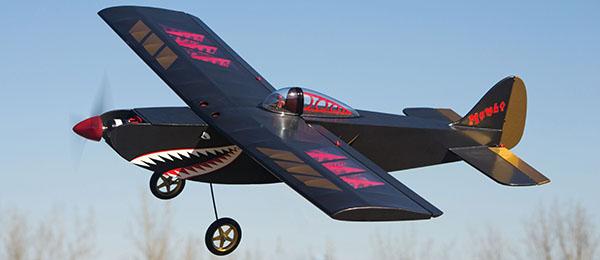
With Lewis Schwab at the controls we flew the Stinger on February 5, 2012 in a light breeze and balmy (Long Island in Feb.) 45 degree weather. After checking balance, control directions and trims we checked static draw and watts. We recorded slightly over 1100 watts and a static draw of around 54 amps.
The battery was not ‘hot’ off the charger so that may vary with temp and charging changes. It was certainly more than the average 150 watts per pound that we figured we needed to get the performance we expected.
The throttle was advanced and it was airborne in about 30 feet. A nice gentle climb out to about 200 feet and a gentle turn around and back into the wind. Some basic trim was needed and then on to some basic aerobatics to prove out our assumptions.
Most of the flight was carried out at 2/3 throttle or less. It was noted that the ailerons and elevator were a bit quick at the suggested low rate throws but very manageable. Half to 2/3 throttle flies the Stinger in the 65 to 75 MPH range, full throttle close to 85 MPH. Full throttle provides what looks to be almost unlimited vertical.
Landing requires throttle management as this “Box Car’ settles quickly when the power is removed. It is however quite docile if you prepare for it. From a foot above the ground pull the nose up and it three points beautifully.
Flight notes:
Battery and motor just warm to the touch. Approximately 7.5 min. flight took just over 2000 mils out of the battery.
Lewis noted that torque is a factor and that he needed to ‘stand’ on the right rudder at takeoff. Possibly a touch nose heavy also. We also want to try a couple of different props.
We also decided that the brake needs to set off as the airframe produces a ton of drag by itself.
We will keep you posted on the trials.
This is by no means a 3D airplane but it will be a fun sport plane to throw around the field and is ‘fully aerobatic’.
Notes:
1. Ongoing discussions with various sources have indicated that Great Planes is planning an EP version of the Stinger. They also seem to indicate that there will be a change to the airfoil (drag reduction) to allow for use of a higher KPV motor and 4S battery pack.
These are sensible changes considering that GP wants to couple the Stinger with products they sell. The changes will alter the performance envelope from that of the original and the conversion. I am not saying that is a bad thing, I’m just pointing out that it will fly in a different performance envelope.
2. With regard to electric aircraft in general and conversions in particular it is my belief that one should utilize a power package that exceeds the base requirements by as much as is practical without incurring a weight penalty.
This approach provides a margin of safety and will in the long run provide longer flight times as it allows partial throttle settings to be used throughout the flight. The example is that we assumed 6lbs.5oz. to be our all up weight Motor Calc told us that ‘fully aerobatic’ performance could be achieved with what amounted to 950 watts we ended up with a slightly lighter all up weight and over 1100 watts to work with.
Construction/assembly Notes:
1. Depending on the battery of choice you may not need any tie down. Mine is held in place by the spar tube and foam blocks fore and aft.
2. You may or may not need the thin foam under the battery. Do however use the card stock or mat board as a floor for the battery. It makes it easier to get the battery in and out.
3. The vertical laser scribed line on the firewall is used to center the engine mount for the glow engine if used. It is offset to the left side of the fuse so the crankshaft is centered. The outrunner mount must be centered on the firewall.
4. The LiPo of choice can be moved back and forth quite a bit to aid in obtaining the CG.
5. As long as you can balance the airframe with your choice of power anything that will produce at least 150 watts per pound will fly the Stinger quite nicely. You may have to takeoff at full throttle and your flights may be shorter but the performance should be very close to what we observed.
To conclude, I would like to encourage anyone who has wanted to try converting a glow or gas powered R/C aircraft to give it some serious thought. It’s clean and quiet and not as difficult as you might imagine. There is plenty of help available on the web. Don’t hurry and do some research and you should make out ok.
Sources:
Balsa Products
www.bphobbies.com/catalogue
GWS Products
www.gwsus/english
Eflite/Horizon Hobby
www.horizonhobby.com
Great Planes
www.greatpalnes.com
Castle Creations
www.castlecreations.com
APC Props
www.apcprop.com


Comments
Add new comment