
Written by A.G. "Andy" Lennon
Match a model’s performance to a pilot’s skill level
How to Do It
As seen in the June 2007 issue of Model Aviation.
Definitions for the Beginner
Altitude: Air density reduces with altitude. This is reflected in the constant number in the thrust formula. Altitude (Feet) Constant Sea Level 0.000011127 1,000 0.000010806 2,000 0.000010490 3,000 0.000010182 4,000 0.000009881 5,000 0.000009581 6,000 0.000009301 ARF: Almost ready to fly. BHP: Brake horsepower. CID: Cubic inch displacement. mph: Miles per hour. PLF: Propeller Load Factor (diameter2 x pitch). PL: Power loading (ounces of model weight per cubic inch of displacement). rpm: Revolutions per minute. Stability: A model’s ability to return to level flight after a gust or when controls are centered. Torque: Turning force in inch-ounce. Trim: Adjust controls for level flight. TWR: Thrust-to-weight ratio (measured in percentage). Wing area: Constant chord-chord x span (in inches) Tapered-(Root Chord + Tip Chord) x Span ÷ 2 Divide square inches by 144 to get square feet. Wing loading: Ounces of model weight divided by the wing area in square feet. The result is ounces per square foot of area.Image
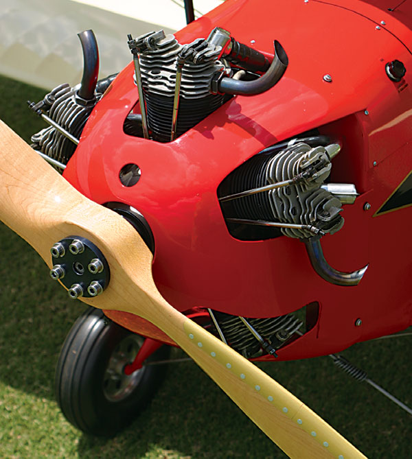
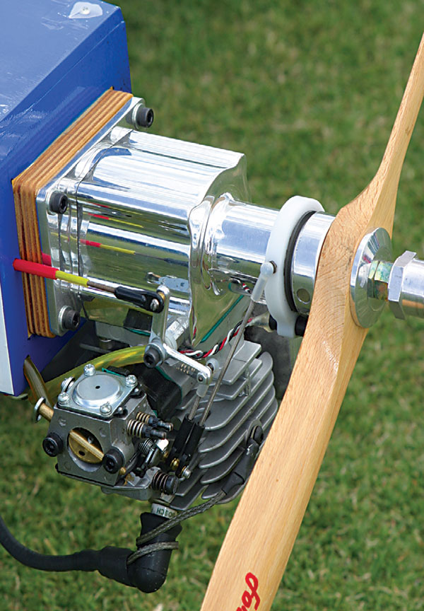
Scale aircraft have engine needs that often go beyond propeller selection. Engine sound adds realism, and selecting the right combination can improve judging scores.
Matchmaking
Matchmaking proposes a logical engineering approach to selecting a model, engine, and propeller, and the combination’s performance and flying characteristics will be a match for the pilot’s flying-skill level—or for a beginner with no flying skills at all. This article includes simple formulas involving public-school arithmetic that are easy to solve on an inexpensive pocket calculator. It needs to be the “scientific” type, which has square (x2) and square root (√) buttons. The article is divided into sections that cover the model, the engine, estimating thrust, selecting a propeller, and information sources. It is aimed toward the beginner but contains information that will be of interest to the expert.Image
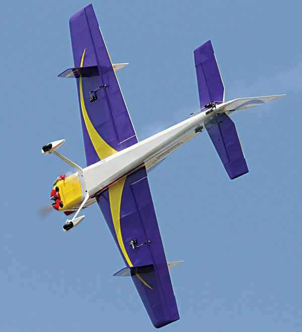
An Aerobatics model requires the right balance of thrust for strong vertical performance, but also needs to be quiet to adhere to AMA noise rules.
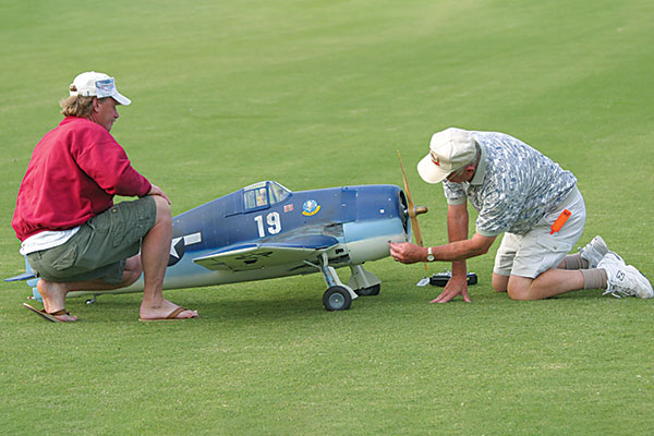
The Model: A beginner needs a stable, relatively slow-flying airplane that virtually flies itself and has limited aerobatic capabilities. Its basic specifications include a .40-size engine, a 700- to 800-square-inch wing area, and a wing loading that does not exceed 20 ounces per square foot of wing area. This aircraft’s airframe will have high drag from an exposed engine and large wheels on its tricycle landing gear, which will allow for a steeper glide slope that makes judging landing approaches easier. It will have full proportional control of the ailerons, elevators, rudder, and throttle. The student is well advised to join a local RC flying club. Most have experienced pilots who instruct. They will check the model for the correct CG location, fully charged batteries, a fueled tank, and correctly functioning controls. The instructors will start the engine and adjust the needle valve for high rpm and idle, and then test-fly and trim the airplane for level flight. They will stand by the novice as he or she flies the model, and they will be ready to take control if problems arise until the beginner has developed adequate skills to fly alone.
Image
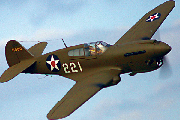
Warbird models are famous for high-speed low passes. The airplane’s smooth outline means it requires a lower-pitch propeller.
The expert flier wants high power in relation to his or her model’s weight, to pull the airplane easily and smoothly through maneuvers that include sustained vertical climbs. The aircraft must have relaxed stability for good aerobatics, and high wing loadings with fast takeoffs and landings are no problem for this pilot. Popular models for the expert are scale versions of aerobatic monoplanes and biplanes, such as the Extra 300 and the Ultimate biplane. RC Aerobatics pilots fall into this category. The rest of us fliers fall somewhere in between the beginner and expert classifications. Table 1 provides suggested parameters for all three classes of pilots. Class Speed (mph) Wing Loading (ounces/square foot) PL (ounces/CID) Two-Stroke PL (ounces/CID) Four-Stroke Expert 100-125 25-35 100-200 90-180 Intermediate 80-100 20-25 200-250 180-225 Beginner 60-80 15-20 250-300 225-270
Table 1
Power loading (PL) is a convenient way to relate weight to power for comparison purposes. A model that weighs 92 ounces and is powered by a .46 two-stroke engine would have a PL of: 92 ÷ .46 = 200 ounces/CIDImage
A two-stroke .46 engine can use any of more than a dozen 9- to 11-inch-diameter propellers. One of those will be right for the aircraft and the pilot combination.
A 175-ounce model powered by a l.20 CID engine has a PL of: 175 ÷ 1.20 = 145 ounces/CID To select an engine’s displacement requires the model’s weight and the PL to be selected. The formula is: Model Weight (ounces) ÷ PL (ounces/CID) = Engine CID For a model that weighs 100 ounces and has a PL of 250 ounces/CID: 100 ÷ 250 = .40 CID engine In my experience a two-stroke PL of 200 ounces/CID permits a sustained vertical climb to almost out-of-sight altitude.
Image
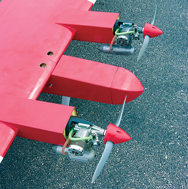
Multicylinder engines have special propeller requirements ranged to suit their limited performance.
The Engine: The power of an engine is expressed in two ways: torque and/or brake horsepower—both at specific rpm. Torque is the elemental force that rotates the propeller. To obtain the maximum thrust, the propeller’s diameter and pitch should load the engine to an rpm of the highest torque.
Image
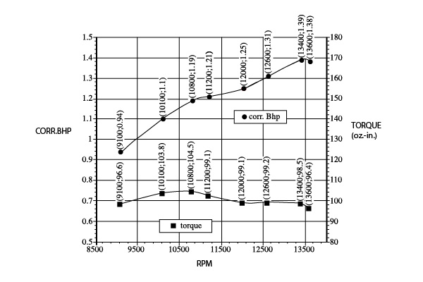
Figure 2a
Figure 2a illustrates the output of a .61 CID engine, which is an excellent sport power plant. The torque curve is almost level, peaking at 10,500 rpm. This engine can effectively rotate a wide range of propeller diameters and pitches: large diameter and low pitch for slow-speed flight or smaller diameter and larger pitch for faster speed. Sport engines operate in a 6,000- 13,000 rpm range. The large engines develop their maximum torque at the lower rpm. Brake horsepower is a calculated figure. It is: Torque (inch-ounce) x rpm ÷ a constant number (engine expert Dave Gierke uses 1,008,000). Increases in either (or both) torque and rpm will result in an increase in horsepower. The rpm figure is increased by using small propellers with low pitch, which reduce the load on the engine. These propellers are too small for practical sport-model flying.
Image
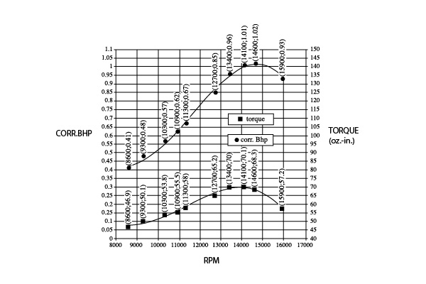
Figure 3
Some engine manufacturers have adapted racing-engine technology to their power-plant designs. That moves the peak of the torque curve closer to peak rpm, further inflating the horsepower output, but to the detriment of torque in the sport rpm range. See Figure 3. The automotive people are more candid. They advertise horsepower and torque, such as “200 horsepower at 6,000 rpm = 275 foot-pounds of torque at 4,400 rpm.” Ads in model aviation magazines quoting “1.6 horsepower at 16,000 rpm” have little significance for practical propeller selection. Torque is the figure to use. Model engines fall into the three following groups. 1) The engine has had a review published that provides the horsepower and torque curves along with a tabulation of rpm for a range of suitable propeller diameters and pitches for that engine. Figure 2 (a and b) is typical. 2) The engine has been reviewed, but only the tabulation of propeller rpm is quoted. 3) The engine has not been reviewed. APC Propeller Diameter x Pitch rpm Thrust (ounces/second) Speed (mph) 11 x 7 13,400 126 110 12 x 6> 13,400 115 82 12 x 8 10,500 134 95 12 x 6 10,100 133 80
Figure 2b
Thrust Estimating: A propeller rotating at high rpm blasts a column of air backward. The equal and opposite reaction (Newton’s third law of motion) propels the airplane forward. The air coming off the propeller has volume weight and velocity. Air weighs 1.22416 ounces/cubic foot at sea level. It is possible to calculate the weight of this air blast, providing thrust/second. I have developed a simplified formula for thrust estimating. It is: Diameter2 (inches) x nominal pitch x static rpm x .000011127 = thrust in ounces/second at sea level (See altitude definition for modified constants for high altitudes where air weight is lower.) A 10-inch-diameter, 9-inch-pitch propeller turning at 12,000 rpm would have a thrust/second of: 102 x 9 x 12,000 x .000011127 = 120 ounces/second Knowing the model’s weight and the thrust/second, it is possible to determine the thrust-to-weight ratio (TWR), measured in percentage. A 92-ounce model (my Swift) with a thrust of 120 ounces/second has a TWR of: 120 x 100 ÷ 92 = 130%
Image
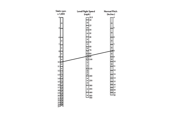
Figure 1
Figure 1 estimates the model’s speed using the propeller’s nominal pitch and rpm. The TWRs are calculated for 14 models’ performances I have observed many times. It was concluded empirically that the TWR is proportional to the angle of climb the model can sustain indefinitely. See Table 2. Class TWR Performances Expert 110% and up Sustained vertical climb, high maneuverability Intermediate 85 to 110% Sustained steep climb, good maneuverability Trainer 65 to 85% Modest climb, low maneuverability Glow-Powered Glider 25 to 65% Shallow climb, poor maneuverability
Table 2
TWR percentages are a more accurate appraisal than PL because engines with the same CID but different manufacturers are not equally powerful. If you have an engine and are seeking a model for it to power, the TWR may be used. Assuming a thrust of 134 ounces/second: TWR Model Weight (Ounces) 125% 107 100% 134 75% 178 50% 268 The formula is: Thrust/Second ÷ TWR = Model Weight That torque should be used for propeller selection. Consider the MDS .46 engine. Table 3 tells the story. Propeller (Diameter x Pitch) rpm Thrust (ounce/second) Model Speed (mph) TWR (100-ounce model) Max Torque 10 x 9 10,710 107 110 107% Max Horsepower 9 x 4 18,000 65 80 65%Table 3. This presents solid proof that choosing a propeller diameter and pitch that loads the engine to peak torque rpm is superior to loading it to peak horsepower rpm.
Propeller Selection: The objective is to select a propeller with a diameter and pitch that loads the engine to or close to its peak torque and propels the model, in level flight, at the preselected speed. The procedure is different in each of the three engine groups I listed previously. Group 1) Brake horsepower, torque curves, and rpm table available.Image
Gas-powered engines are simple to run. This 2.4 cu. in. Fox typically turns a 20 x 10 propeller.
Refer to Figure 2 a and b. Propeller selection is easy. The maximum torque is 10,500 rpm. The rpm table shows that a 12 x 8 APC propeller turns at 10,500 rpm. However, at 8-inch pitch and 10,500 rpm, Figure 1 indicates a speed of 95 mph. This is too fast for our pilot; he or she wants 70 mph. Referring to Figure 1 again, a 6-inch pitch at 10,500 rpm gives 70 mph.
Image
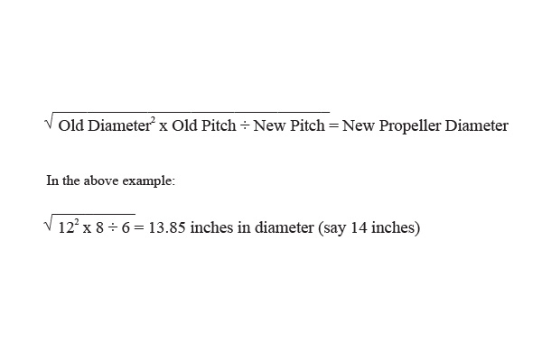
Figure 4
To determine the propeller diameter with a 6-inch pitch that will provide the same load as the 12 x 8, see Figure 4. It is based on Dave Gierke’s Propeller Load Factor (PLF) of Diameter2 x Pitch = PLF. Applying this to the 12 x 8 propeller produces a PLF of 1,152. For the 14 x 6 the PLF is 1,176, which is close enough for all practical purposes. If the expert pilot requires a higher speed than 95 mph, he or she will follow the same procedure, but select a higher pitch, at the same rpm (10,500) that will give the required speed and use the formula to obtain diameter. Group 2) Only rpm table available.
Image
Maximum rpm from an engine isn’t always practical; that demand could cause serious damage over a long period.
Refer to Figure 2b: the table of rpm for a .61 engine, calculated thrust, and speed. The 12 x 8 gives the most thrust, but notice how close the others are in thrust and note the speeds. For our pilot who wants 70 mph, proceed as in Group 1 to obtain pitch + diameter with a PLF that is close to that of the 12 x 8 propeller. Group 3: No published review. Unless you have a friend, with the same engine, who can be persuaded to develop an rpm table (Figure 2b) for suitable propellers, the only thing to do is obtain the engine and bench-test it to develop an rpm table specifically for that engine—after carefully breaking in the new engine.
Image
An aerobatic model has a wide performance range. The optimal propeller for slow-speed 3-D isn’t necessarily the right propeller for precision flight.
Then proceed as for Group 2, calculate thrust/second, and estimate speed from Figure 1. Select the propeller that produces the highest thrust. It will be close to the engine’s peak torque. Modify the diameter and pitch to obtain the selected level flight speed, as detailed in Group 1. Information Sources: To assist the beginner in the selection process, following are sources of information. • Engine, kit, or ARF reviews in model aviation magazines. • Catalogs from distributors such as Tower Hobbies. They contain a wealth of information about models, engines, propellers, and hundreds of accessories. • Dave Gierke’s thorough and comprehensive engine evaluations published in Model Airplane News: “.40 Engine Shoot Out” in the March 2001 issue and “We Test 10 .60 Engines” in the May 2003 issue.
Image
A 60-size model will often fly as well with two .25 engines (less displacement).
Thanks to friend and fellow author Dave Gierke; his work made a major contribution to this article. Happy Landings! -A.G. Lennon 487 Oakville Rd. Dollard-des-Ormeaux Quebec, Canada H9G-1M1


Comments
Errata
The thrust (oz / sec) figures in Table 3 seem 100x too high. (10k and 18k oz?)
Re: Errata
PS Actually, Table 3 is all messed up, all column labels need to be shifted right one column.
Andy Lennon
I am proud to say that I counted Andy Lennon as a friend! He was one of the foremost model aerodynamicists of our time, and his passing several years ago was a great personal loss. He was as mentally sharp at the age of 94 as anyone I have ever known... at a third his age. For those who wish to get the straight story about how and why an airplane flies, Andy's wonderful book on Model Aerodynamics is still available through Air Age Publishers (Model Airplane News).Rest in peace my friend... Dave Gierke
Showtime pictured:
The Showtime you pictured was a model I owned right up until I forgot to put the antenna up and was coming in for a landing after about 8 minutes of flight. Needless to say, it was destroyed trying to fly through a maple tree. It was the smoothest and most stable airplane I ever had. Wished they still made them. Originally it had a .61 OS Max engine in it, until I decided to shove a Super Tiger .90 engine in it. The performance was spectacular. I loved that plane. I have one request. Bring it back into production.
This treatment of thrust and
This treatment of thrust and the associated aircraft speed is fundamentally incorrect. Figure 1, for example takes no account of aircraft drag - it predicts the same speed for a high drag trainer as for a streamlined aircraft given the same static rpm and propeller pitch. And it is based upon static rpm - in flight rpm will be higher when using a I.C. engine. The correct treatment requires a calculation using a propeller thrust coefficient. The method is detailed on the A.P.C. website under technical information, performance data. Thrust typically decreases with increasing flight speed; at the same time aircraft drag increases. An estimate of level flight speed is produced when the thrust equals the drag.
Add new comment