
Written by Dan Gaston
Dave Platt’s classic design, updated for electric RC
Product review
As seen in the October 2017 issue of Model Aviation.
Bonus Video
Specifications
Model type: Kit Skill level: Intermediate Wingspan: 42 inches Wing area: 400 square inches Length: 34 inches Weight: 20 ounces Construction: Wood; Coverite Price: $99.75 Requires: Four-channel radio and receiver; two servosTest-Model Details
Motor and ESC: E-flite Park 370 motor; Castle Thunderbird 36 ESC Battery: Thunder Power 3S 1,350 mAh and Ready Made RC 2S 1,300 mAh LiPo batteries Propeller: GWS 8 x 4 Radio system: Spektrum DX8 transmitter; Lemon Rx six-channel receiver; two Futaba S3114 servos Ready-to-fly weight: 18.25 ounces (2S); 19.05 ounces (3S) Wing loading: 41.9 ounces per square foot Flight duration: 7-plus minutesPluses
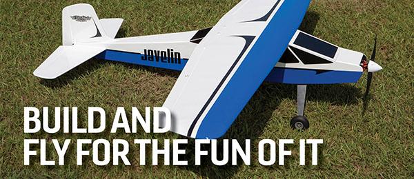
• Full-size rolled plans. • Color-printed instruction manual. • The kit includes nearly everything necessary to complete the model. • Just beautiful in the air.Minus
• Discrepancies among the plans, instructions, and parts.Product Review
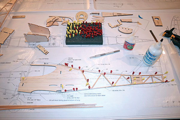
It’s hard to believe that it’s been more than 20 years since I first saw the original Satin Doll on the cover of the January 1996 issue of Flying Models magazine. That issue is still on my shelf and the Dave Platt-designed Satin Doll has lost none of its appeal in the last two decades. Those two decades have also proven me to be a professional-level procrastinator because I still haven’t built one. In the early spring of 2017, I ran out of excuses because BMJR Models announced its new electric RC Satin Doll kit. I immediately fired off an email to Brian Malin (the talented man behind BMJR) to see if he could bring a kit to the Weak Signals Toledo Show: R/C Model Expo in April. The show weekend finally arrived and there, along with a selection of its other fine kits, was a stack of Satin Doll kits. My first impression of the kit was how much model airplane there is for such a reasonable price. In fact, it takes two boxes to hold everything. In addition to the 22 beautifully laser-cut sheets and dimensional wood stock bundle, there is a comprehensive hardware package. This package is complete to the point of including wire-in-tube pushrods, wheels, prebent landing gear, hinges, control horns, and much more. There are two full-size, rolled plans sheets and a color instruction manual, so there’s no need for a laptop on the workbench.Image
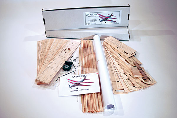
This shows the contents of the kit. It is a lot of model airplane for the money.
Before beginning the construction of any model, it’s always advisable to pour over the plans and any included written instructions to familiarize yourself with the order of the build and any procedures that may be new to you. This does not guarantee a snag-free build, but it can help you avoid building yourself into a corner. During the build, I used my usual selection of CA glue, aliphatic adhesives, and epoxy; however, this time I tried new glue from Deluxe Products called Super ’Phatic, which I’ll write more about later. I’ve been using Deluxe Products Cover Grip to apply non-adhesive-backed coverings for some time, so I felt confident concerning this new glue. At this point I want to state that this is absolutely not a beginner’s kit. A basic understanding of construction methods and procedures is a must. The manual begins with the construction of the upper wing. There are a few typos in the manual within the first few steps, but these mistakes are easily figured out by referencing the accompanying photos and/or the plans. The wing’s trailing edge (TE) was one such point of confusion. The manual calls out one size, the plans call out another size, and the supplied TE stock is yet another size. The builder needs to work with the TE stock in the kit, which matches the drawn size on the plans, but again, not the callout. The builder is given the choice of notching the TE stock to accept the ribs or sanding a similar amount off of the rib’s TE and settling for a butt joint. I chose the stronger method of notching the TE using a jigsaw blade with a wide kerf that just happened to be 1/16 inch.
Image
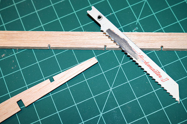
The author used a wide-kerf jigsaw blade to slot the TE to accept the ribs.
Here is where I tried the Deluxe Products Super ’Phatic glue. To say that I was impressed is an understatement. This aliphatic glue wicks into joints as though it was thin or medium CA glue, sets up quickly, and results in a strong, flexible joint like a “normal” aliphatic. The balance of the upper wing construction is straightforward, thanks to the laser-cut ribs and simple laminated leading edge (LE). Before gluing on the laminated LE, take the time to sand the slight bevel on the nose of the ribs. The wing’s center section had another issue with TE sizes. The center section ribs are cut according to the shown 3/4-inch TE, but the supplied TE stock is only 1/2 inch. My solution was to simply glue some 1/4-inch square stock from my scrap box to the TE to make it measure 3/4 inch. This was then notched for the center rib and sanded to the TE profile after the center section was finished. I sanded the wing panels before joining them to the center section, which included fairing the ribs into the TE and rounding the LE and wingtips. The charred edges of the laser-cut ribs help let you know when you’ve sanded enough because the darkened edge disappears.
Image
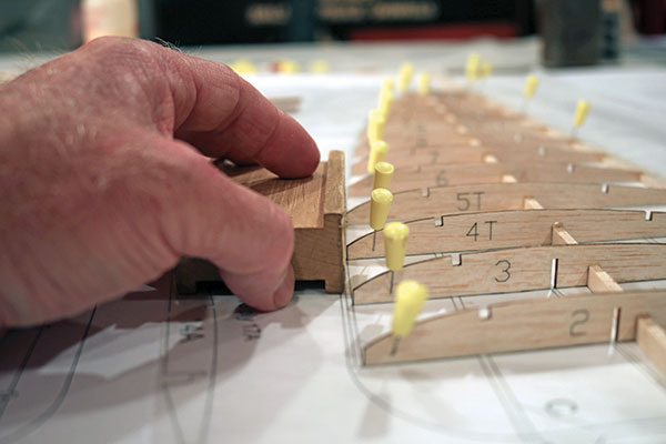
Take the time to sand a bevel on the rib snouts for a better, stronger joint with the laminated LE.
When joining the panels to the center section, the manual says to prop up the panel 1.5 inches at rib number 13. This left some of the plywood dihedral brace protruding below the bottom of the ribs. I found 1.25 inches at rib number 13 to be ideal and this brought the dihedral brace into perfect alignment with the bottom of the wing panel. The lower wing construction mimics that of the upper with the exception of the center section and the manner in which it mates to the outer panels. Again, it’s not difficult, but a builder must pay attention to all of the information available in the plans, photos, and written instructions. I could have finished the wing in a much shorter timeframe, but I admit to spending time simply admiring that wonderful shape pinned to my building board. The tail components are straightforward and hardly warrant mentioning, but there is one feature that might seem odd simply because it goes against convention. There is an elevator on only one side of the horizontal stabilizer.
Image
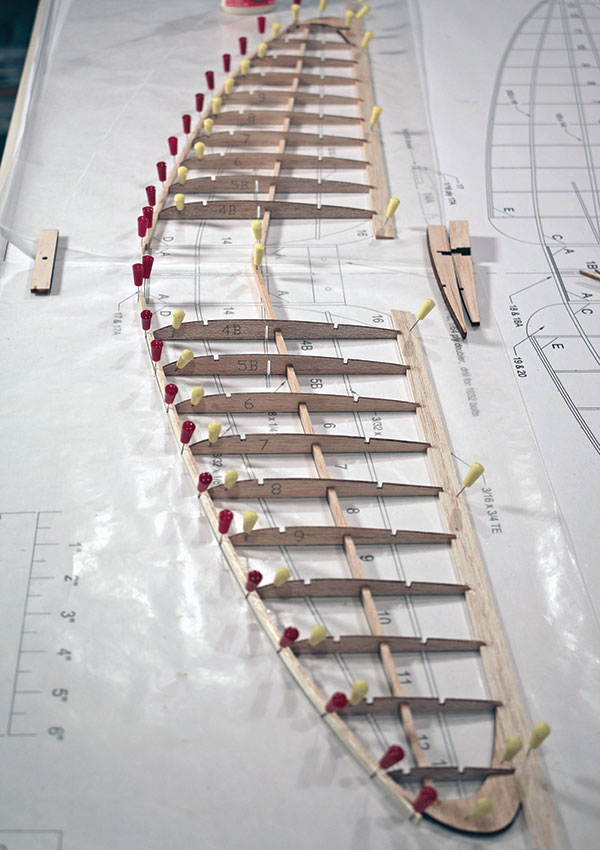
The classic wing shape of this biplane is appealing.
I’ve been doing this on all of my converted Free Flight builds, and I can assure you that it has no negative effects on the flight characteristics. In this case, the TE of the horizontal stabilizer is V shaped, which would require two servos to drive the elevators because they are not aligned. My reason for always having done it this way is far less technical—I’m just lazy that way. The fuselage structure is a nice mixture of old-school stick construction and modern laser-cut, tab-in-slot construction. There’s a lot going on in the forward section of the fuselage, so I strongly suggest that you dry-assemble it first. The manual suggests a certain order of assembly and if you follow it, there should be no problems. The balsa and plywood cowling would be an alignment nightmare to assemble were it not for a simple, but brilliant, cruciform jig that the 10 individual pieces simply slide over and are glued as they are stacked. After the glue has set, the jig is removed and the eight 1/4-inch balsa layers are sanded to follow the fore and aft plywood layers. The cowling is secured to the fuselage using the supplied rare-earth magnets. The motor mount is composed of an inner and outer plywood box. The motor is mounted to the inner box, which slides inside the outer box to allow fore and aft adjustment before gluing in place after the proper spinner clearance has been established. When it was time to attach the tail feathers, it seemed to be open to the builder’s preference. Again, this is where having previous building experience will allow you to breeze through the job after some studying and planning.
Image
The BMJR Satin Doll is a great mix of old-school stick-built and modern laser-cut construction.
After all of the individual components have been built, it’s time to sand everything to final shape and surface smoothness. Anything you leave rough at this point will be magnified through the covering, so take the time to do it right. I chose Coverlite covering and applied it using Deluxe Products Cover Grip and a modeling covering iron and heat gun. Cover Grip is a water-soluble, heat-activated adhesive that is brushed onto the wood wherever the covering needs to be adhered. I left the covering in its wrinkled state until the final assembly before the maiden flight. There is a statement in the instruction manual concerning the negative effects of a warped wing. Believe it!


Comments
Add new comment