
Written by Dan Gaston
A larger rendition of a Bob Selman design
Product Review
As seen in the October 2018 issue of Model Aviation.
Bonus Video
Specifications
Model type: Laser-cut kit Skill level: Intermediate Wingspan: 40 inches Wing area: 360 square inches Flying weight: 32 to 35 ounces Price: $129.50Test-Model Details
Radio system: Spektrum DX18; Spektrum AR6210 receiver; Tactic TSX5 servos Power system: Cobra 2808/30 1,000 Kv motor; Castle Creations Talon 25-amp ESC; APC 8 x 4E propeller; E-flite 3,200 mAh LiPo batteryPluses
• Computer-drawn manual. • Incredibly simple construction. • Great flight envelope—mild to wild. • Full hardware package included.Minus
• Landing gear is rather flexible; could stand increased wire diameter.Image

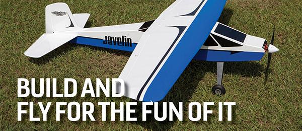
The Dave-E is a gentle flier on a 3S LiPo battery and a rather capable aerobat on a 4S battery.
Product Review
I’m beginning to wonder if the people at BMJR Models ever rest because it seems as though they introduce a new kit every other month. Anyone bemoaning the lack of kits available today hasn’t visited the BMJR website. With more than 100 kits ranging from rubber-powered aircraft through D Gas Free Flight, RC of all sizes and styles, and Control Line, the company is sure to have something to suit your fancy. The Dave-E kit reviewed here is not a scale airplane, nor is it a competition aerobatics aircraft. Its sole purpose is fun. This would make a fantastic first kit build for a post-trainer sport model. In my 45 years in this wonderful hobby, I’ve built hundreds of kits, and I will state that the Dave-E is one of the, if not the, easiest-built kits yet. If you’re on the fence about trying a first kit build, get down off the fence, order a Dave-E kit, and dive in. The kit consists of no fewer than 39 sheets of laser-cut balsa and plywood, assorted sheet and strip stock, and the usual BMJR complete hardware package that even includes the wheels. The clearly printed, computer-drawn instruction manual begins with the fuselage construction. I always suggest that you take time to read the entire manual to familiarize yourself with any procedures that might be new to you. In the case of the Dave-E, step one will allow a builder to make a critical mistake if the directions are not followed. The last line of instructions in step one warns a builder to make one left and one right side. That age-old warning seems ridiculous and unnecessary, until you find yourself staring at two identical right sides. The fuselage goes together like a simple wooden jigsaw puzzle without the mystery of what piece goes where. This kit goes so far as to provide laser-cut, interlocking, crossgrain sheeting for the fuselage bottom. Each step clearly shows the addition of a few more pieces until you are holding a completed fuselage with a built-up wood cowling. It really is as easy as tab-A-into-slot-B-style construction. The only change I had made so far was the addition of a crossbrace between the fuselage sides in the large hatch opening area. This was necessary to keep the fuselage sides from bowing out and not matching the hatch lines. A fair amount of sanding is required in a couple of areas such as the top deck, headrest, and cowling. For situations such as these, where thick sheet or block requires shaping, I use a 10-inch semirigid foam sanding block with 36-grit sandpaper. Care must be taken when using such coarse abrasives because they will devour balsa and skin at an alarming rate. Immediately following the fuselage construction is that of the wheel pants. The Dave-E can, of course, be flown without the wheel pants, but the difference they make in the model’s appearance is worth the effort. Each pant is made up of 16 individual pieces, including plywood plates used for mounting and positioning. The final shape of the wheel pants is up to the builder because it depends on how aggressively the previously mentioned 36-grit sanding block is applied.Image

The wheel pants are shown in three stages. The finished pant with sealer, filler, primer, and paint weighs less than the sum of its raw parts.
Before proceeding to the construction of the tail, I applied Polycrylic to the cowling and wheel pants. These are solid balsa sheet assemblies, which I knew I wasn’t going to cover with Coverlite like the balance of the airframe. By starting the sealing process now, I could fill, sand, and prime in between building sessions and they would be ready for paint when everything else was to that point. Assembling the tail group is straightforward, using only laser-cut perimeter and center base pieces with 1/16 x 3/16-inch balsa strip stock for the internal “ribs” and diagonal bracing. This construction style can be made simple by using a miter sander. Not only does it simplify the building, but it makes for stronger, better-fitting joints. A few minutes after beginning, the tail surfaces were built and ready for sanding. If you don’t take the time to sand these structures now, the covering will magnify every little glue spot and joint transition. To block-sand such structures without fear of twisting and breaking them, I laid the part on top of a sheet of 120-grit sandpaper and block-sanded it, flipping it a number of times to avoid creating thin sections. The underlying sandpaper does not allow the part to move, twist, or break. When everything was satisfactorily smooth, I hinged the rudder and elevators with strips of old computer floppy disc material. This is about as large a model with which I would trust this type of hinge. The wing contains one of the coolest features I’ve seen in a long time. The spar itself is laser cut to size and shape with slots, notches, and some strange-looking cutouts. Those odd-shaped holes allow the full-length ribs to slide into the spar horizontally, twist 90°, and rest against stops, leaving the rib perfectly placed and aligned vertically. Brilliant!
Image

Could it possibly get any easier to build a wing? This is brilliant!
Before anything is glued, pay special attention to ensure that the angle on the root end of the spar will lean that rib in the correct way to produce dihedral, not anhedral. Forward of the spar and between the full ribs, are false ribs. The directions have the builder place the false ribs in the spar, followed by inserting the leading edge (LE) into the slots in all of the full and false ribs. My only deviation from the wing instructions was here. I placed the false ribs on the LE and then slid the assembly into the full ribs and spar. The trailing edge (TE) is made up of two sheets of 1/16 x 1-inch balsa: one upper and one lower. With a symmetrical wing, this would normally mean that the builder had to elevate this, shim that, and in the end, just hope for a twist-free wing. The Dave-E’s ribs have a riser at the rear through which they can be pinned to the board. Slightly above the riser is a slot into which the builder slides the lower TE edge sheeting and glues it to the rib. Another plus for this wing is the utilization of diagonal ribs aft of the spar between the main ribs. These few, partial ribs—only four per wing half—add tremendous torsional rigidity to the wing. After the diagonal ribs and a few other items are in place, the upper TE sheeting is glued into position along with the laser-cut, interlocking, center section sheeting. Just like the rest of the Dave-E kit, constructing the wing is as easy as following the illustrated instructions. At this point, I installed all of the radio and power systems. The radio installation is made simple because of the rudder and elevator servos being placed in the fuselage sides at the tail within laser-cut plywood doublers. There are no fiddly pushrods to mess with.
Image

With the rudder and elevator servos in the tail and the aileron servos in the wing, the receiver, ESC, and battery are lost in the cavernous fuselage.
The aileron servos are installed in laser-cut boxes that were built along with, and as part of, the wing. Again, there is nothing but short, direct linkage for a slop-free and trouble-free setup. The motor is mounted to a built-up plywood box that slides over a firewall-mounted plywood box. The adjoining faces of the boxes were coated with 30-minute epoxy and the motor slid into place. The cowling was then snapped into place and some scrap 1/16-inch balsa was tacked to the front face. Next, the motor was pulled forward—actually upward because this operation is done vertically—and the spinner installed. Finally, the motor/spinner are pushed in and aligned until they rest on the scrap balsa spacer. I stood the assembly in a corner until the epoxy had completely set. The ESC, receiver, and battery compartment is nothing short of cavernous, so there were no worries about where to put things. I used all of the included hardware and it has proven to be up to the task. As previously mentioned, the cowling and wheel pants were sealed in three coats of Polycrylic, sanding between each coat with 220-grit sandpaper. This was followed by Rust-Oleum sandable primer smoothed with 400-grit sandpaper until a paint-ready surface was achieved. CoverLite was used to cover the fuselage, tail, and wing. Deluxe Materials Cover Grip (slightly thinned) was used to secure the nonadhesive-backed CoverLite to the perimeter of the open bay structures, and all of the sheeted surfaces. In a previous build, I attempted to save weight by not coating all of the sheeted surfaces and only securing the covering to the edges. The sagging, billowing results were not worth any of the weight savings. The only exception to this process was the ailerons, which I covered in doped silver tissue. There was no critical reason for doing so; it was simply easier for me. The blue trim was painted on using rattle-can Rust-Oleum 2X spray paint.
Flying
It was a terrible spring for flying here in north central Ohio. Normally, it’s not a good idea to make your first flight of the year a new airplane’s maiden flight, but the weather dictates these things for us. So, with rusty thumbs I advanced the throttle and watched the Dave-E lift off nice and gentle into a shallow climbout … perhaps a little too gentle and shallow. I’m a firm believer in flying on the wing and not overpowering a model, but I had either under-propped the motor or not supplied enough voltage to spin up the low-pitch propeller. The Dave-E flew in a relaxed manner, but left no margin for error when throttled back. Still, rolls and loops were possible; they required some energy-management style of flying. Because I didn’t have a higher-pitched propeller with me, I borrowed one of my son’s 4S LiPo batteries. That was all the Dave-E needed to become an entirely different airplane. Now it was capable of any maneuver this side of 3D, yet when throttled back, it reverted to a nice, gentle flier. I’m continuing to experiment with different propellers to find the right mix of power and speed on a three- or four-cell setup. That’s the fun part.Image

Without those shapely wheel pants, the Dave-E would lose a lot of character.
—Dan Gaston [email protected]


Comments
Purchase of Dave E motor mount parts from Assembly Guide List
from #22 AD - Motor Mount Parts. How do I order one sheet of AD, 4" by 18" - 1/16th plywood sheet or do I need to purchase 4 of the same as listed in the kit list. Thanks for your assistance. Charles Ramos -780 NW Meadowood Circle, McMinnville, OR 97128
Add new comment