
Written by John Pomroy
A nicely detailed ARF warbird
Product review
As seen in the July 2017 issue of Model Aviation.
Specifications
Model type: Scale warbird Skill level: Advanced Wingspan: 60.4 inches Wing area: 610 square inches Length: 44.5 inches Recommend power system: .46 two-stroke or .70 four-stroke engine, or equivalent electric motor Needed to complete: Radio equipment, engine or motor, and accessories Construction: All wood with fiberglass cowl Covering: Printed film Street price: $219.95 (retracts not included; VQ custom electric retracts $99.95)Test-Model Details
Radio used: Futaba 14SG; four Hitec HS-5485HB; four Hitec HS-5070MH servos Power system used: Tacon Bigfoot 4020 670 Kv BLM with Turnigy Plush 60-amp ESC; Turnigy 4S 4,500 mAh 40C LiPo battery Flying weight: 8 pounds, 3 ounces Flight duration: 5 to 7 minutesPluses
• Panel line and rivet surface details printed on matte film covering. • Large removable top hatch for easy equipment access. • Plenty of space for up to a 6S 5,000 mAh LiPo battery. • Fully finished cockpit with painted pilot figure installed. • Great-quality hardware. • Excellent flight qualities.Minuses
• Flying weight is high for a model of this size. • Non-locking hardware provided to secure the motor firewall.Product Review
The Grumman F6F Hellcat was the U.S. Navy’s dominant World War II fighter in the second half of the Pacific War. The F6F was designed from the ground up to counter the Japanese Mitsubishi A6M Zero because its predecessor, the F4F Wildcat, was no match for the Zero. Using the same engine as the F4U Corsair—a Pratt & Whitney R-2800 Double Wasp—the Hellcat could fly faster and climb better than the Zero could above 14,000 feet. By the end of WW II, the Hellcat-to-Zero kill ratio was 13:1. It was built to take damage and was reported to be well-behaved and enjoyable to fly. More than 12,000 were built in slightly more than two years. Although the aircraft was ultimately phased away from the frontlines, it served for another decade after WW II as a night fighter and was the first aircraft used by the U.S. Navy’s Blue Angels official flight demonstration team at its formation in 1946. As of 2017, there are seven full-scale Hellcats in flying condition—one in England and six in the US—and four more currently undergoing restoration in the US.Initial Impressions
VQ Warbirds offers the Hellcat in two sizes: 72-inch and 60-inch wingspan versions. This review is of the 60-inch version. Upon opening the carefully packed 35 x 24 x 10-inch box, it became quite clear that this ARF is a cut above the rest. All of the major components have full panel lines, rivets, service hatches, and other superb surface detailing printed on the covering. Add to that a top-quality, three-tone matte color scheme found on most period Hellcats, a fully detailed cockpit with a preinstalled, painted pilot bust, elevator, and rudder structures that result in a scale scalloped covering appearance, and you know this model will stand out from the rest before you even start assembly!Image
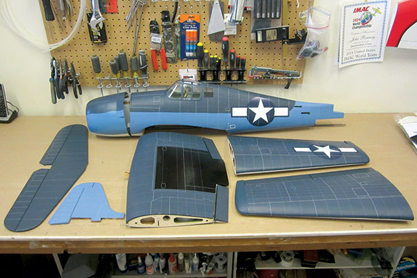
Beautiful, intricate surface detailing is printed right onto the covering for all of the airframe’s major components.
After carefully removing each of the individually wrapped airframe components, I was further impressed with the craftsmanship of the underlying balsa structure. The fit and finish of all internal joints and the surface preparation of the wood before application of the printed covering is remarkable. I mean really remarkable! I unsuccessfully searched for 30 minutes, trying to find warps, bows, poorly fitted joints, and surface imperfections—there just weren’t any!
Assembly
The 23-page instruction manual does a great job of eliminating any guesswork during each assembly step. The kit includes all accessory components such as a motor mount, fuel tank, mounting hardware needed to install a .46 two-stroke or .70 four-stroke engine, as well as accessories for installation of roughly any size or type of electric motor. Accessories needed for either fixed or retractable landing gear (except the retracts themselves) are also provided. The instruction manual clearly walks you through the steps without confusion, no matter what options you decide to go with. For this review, I elected to install electric propulsion and the electric retracts offered by VQ specifically for this model. I started with the wing assembly. Each outer wing panel plugs into the center section via an aluminum wing tube and two hardwood alignment dowels. After sliding each outer panel fully into place, drill and tap through the top side outer panel into the aluminum wing tube where a machine screw will later be installed to keep the outer panel from sliding off in flight. This method allows for routine, easy removal of the outer panels for compact transportation to the field.Image
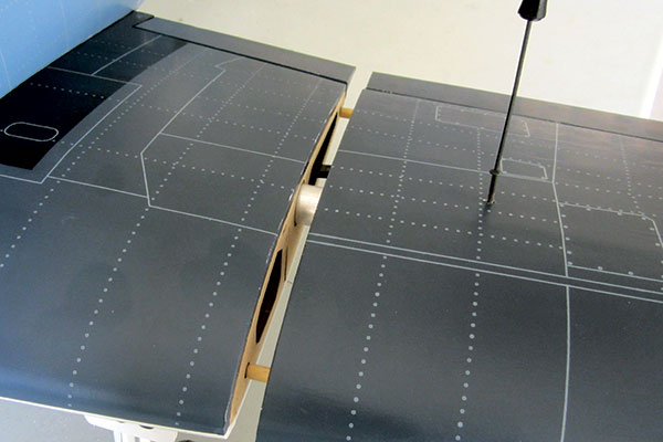
The outer panel slides onto the wing tube. A single screw that tightens down through a tapped hole in the wing tube keeps the outer panel in place.
There are a total of six servos in the wing. There are four for the flaps, for which I chose to use Hitec HS-5070MH digital feather servos—one each for the inner and outer panels. The remaining two servos are for the ailerons, for which I chose Hitec HS-5485HB digital standard servos. The flaps use nice-quality pinned hinges that are permanently installed at the factory. The ailerons have CA hinges installed and glued to the aileron surface side at the factory. The builder only has to do the final gluing to the wing side hinge slots after the linkages are completed. Nice! After installing those, I next connected the VQ retracts to the robust retract mounting rails that were already installed in the center section and painted chromate green. The fuselage assembly begins with the motor installation. The electric motor is mounted to a suspended firewall via four 4-inch 10-32 bolts. The bolts act as adjustable engine standoffs, so almost any electric motor can be easily and properly fitted with respect to the cowl. This method allows adjustment of the axial motor position as well as right thrust and downthrust—clever engineering!
Image
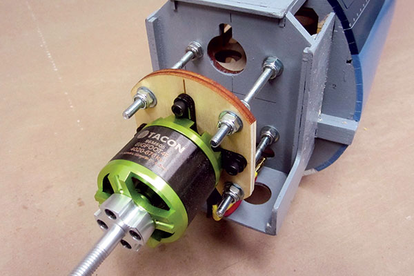
A suspended firewall using four-bolt standoffs allows adjustment of axial motor position, as well as right thrust and downthrust.
The only concern I had was that the kit-provided hardware accomplishes this motor adjustment via nonlocking machine nuts on the front and back of the suspended firewall. No lock washers or other locking hardware was provided to ensure that the nuts won’t vibrate loose under motor running loads. I simply replaced these regular nuts with the locking type. This is an ingenious, flexible, and highly adjustable motor-mounting system. Installing the tail feathers, tail wheel assembly, and radio equipment is straightforward and everything went together flawlessly. The cowl is held in place by four small wood screws in preinstalled hardwood blocks on the fuselage. There’s also a nice compartment between the firewall and first fuselage bulkhead in which to tuck your ESC. In that location, it will get good cooling and won’t clutter the battery compartment. The battery (or fuel tank) compartment is roomy at 7 x 31/2 x 31/4 inches and will easily accommodate up to a 6S 5,000 mAh LiPo battery, or if you choose wet propulsion, a larger fuel tank than the 8-ounce one provided in the kit. Access to the compartment is achieved through a large, top-side, magnetically secured hatch.
Finishing Details
Several nice scale details are provided in the kit, such as landing gear fairings, landing gear foreign object debris covers, pushrod exit fairings, and a fuselage belly pan cover. These parts are a mix of plastic and wood components that are glued together and then attached to the airframe. These steps involve bonding plastic to wood, plastic to covering, plastic to fiberglass, and wood to metal.Image
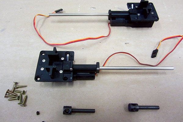
VQ retracts are sturdily built and have worked flawlessly after much bench testing and six flights.
For these types of joints, the best adhesive is Pacer Zap-A-Dap-A-Goo. Whenever I’m faced with the bonding of different materials that I haven’t put together before, Zap-A-Dap-A-Goo is the first thing that I reach for. I used it successfully throughout the assembly and installation of the landing gear’s scale details, attachment of the pushrod exit covers, and even attaching 3 ounces of lead to the inside of the fiberglass cowl.
Final Setup
To balance this model when using a 4S 4,500 mAh LiPo battery required 3 ounces of nose weight. This is the smallest pack you would want to use to achieve adequate flying time. Going to a 5S or 6S 4,500 mAh and/or a larger-capacity battery pack would eliminate the need for any nose weight, while significantly extending flying time. The battery compartment is large enough that shifting the pack aft is easily accomplished if you have a nose-heavy model. I also prefer to use a separate transmitter battery whenever the radio gear setup might push the ESC BEC too hard. This hasn’t happened with the Hellcat, but my concern is the potentially high current demand on the BEC and associated transmitter brownout should either electric retract mechanism jam. Having a small, separate, 700 mAh LiFe battery pack eliminates this risk while adding only 0.8 ounces to the ready-to-fly weight.Image
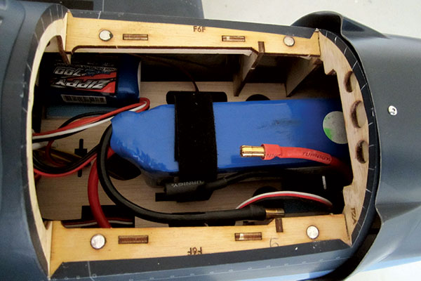
The battery or fuel tank compartment showing a 4S 4,500 mAh LiPo battery installed. The smaller 2S 700 mAh LiFe battery provides separate power for the radio and retracts in this installation.
I also like to verify that my ESC and battery pack are properly sized, so I pulled out my trusty Watts Up? meter to confirm that the full throttle current draw is within the ESC rating of 60 amps. With a freshly charged battery pack, it read slightly less than 50 amps, which equates to a peak power draw of 761 watts. This results in a power loading of approximately 100 watts per pound while spinning the installed APC 14 x7E propeller at 10,000 rpm and should yield roughly 5 to 6 minutes of sporty flying performance!


Comments
F6F Hellcat assembly kit
How long the assembly is taking. I am looking for a kit to keep me busy for weeks. Any advise?
Add new comment