
Written by Chris Mulcahy
Capable and affordable 3-D helicopter
Product review
As seen in the December 2017 issue of Model Aviation.
Bonus Video
Specifications
Model type: Electric flybarless 280-size helicopter Skill level: Beginner to advanced Main rotor diameter: 626mm Tail rotor diameter: 139mm Length: 580mm Height: 170mm Weight: 26 ounces without battery Power system: SAB Direct Drive Motor System Radio system used: Futaba 16SZ Flight duration: 3 to 5 minutes Needed to complete: Flight battery, receiver Price: $449Pluses
• Low parts count. • Inexpensive canopy and tailboom. • Wide performance envelope.Minus
• Tiny parts can be challenging to assemble.Product Review
When I bought my first-generation SAB Heli Division Goblin 700 many years ago, I never imagined that someone would be able to miniaturize it into a 280-size machine. And yet, here we are! SAB had a number of ideas in mind when it designed this helicopter, including a low parts count, an inexpensive repair bill after a crash, and of course, without sacrificing performance. Something that is unique about this aircraft is the direct-drive motor. As the name suggests, it drives the main rotor directly without the need for gears, pinions, or belts, thus reducing the overall parts count.Image
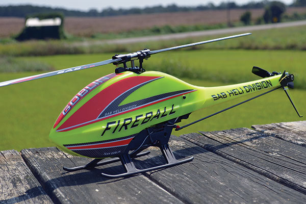
The low parts count and inexpensive replacements make the SAB Goblin Fireball 280 ideal for beginners and pros alike.
The Fireball comes as either a kit and motor, or as a combo that also includes the speed controller and servos. You can’t buy the Fireball without the motor because it is a special motor designed specifically for this helicopter. I built the combo version, which included the three SAB DS12C cyclic servos and the SAB DS12T tail servo. The included 60-amp ESC is also a SAB brand. For my build, I added a Futaba CGY750 gyro (yes, it fit!), a Futaba R3001SB telemetry receiver, and used Pulse 6S 1,250 mAh 75C flight batteries. All of this was guided by my Futaba 16SZ radio.
The Build
As with all SAB kits, the parts are in numbered bags that correspond with each step in the instruction manual. The included manual is a small, full-color printed booklet that guides each step of the build. The first step, believe it or not, is the tail servo. It was at this point that I realized I should plug in my receiver, gyro, and servos, and center the servo arms on each servo. The tail servo is simply sandwiched between the two molded side frames. I then flipped it upside down and added the one-piece molded landing gear.Image
The servos and gyro have been installed.
The tail assembly was next. This is probably the only part of the assembly that will test your patience and dexterity because the parts are tiny! The tail grips contain their own set of bearings and thrust bearings, just like the main rotor head, and each must be assembled. I initially used the same grease on the thrust bearings that I use on all of my helis. I found out that this grease was too much for the tiny thrust bearings, so I removed them, cleaned them, and used a little light oil to lubricate them before reassembly. The tail pitch slider was preassembled at the factory, so there was no need to disassemble it. There are a few preassembled parts, and this is noted in the instruction manual. There is no need to take them apart again. The tail assembly consists of the carbon-fiber vertical fin on one side and an aluminum side plate on the other. The tail is belt driven and the belt must be looped over the tail shaft before final assembly. It is important to mention here that where metal parts screw into plastic parts (such as the uniball into the tail blade grip), the parts must not be overtightened to prevent stripping out the plastic. If you strip the plastic, you will have to replace the part. The tail assembly is attached to the plastic tailboom, which costs roughly $9 to replace. The tail assembly is slotted so you can tension the belt correctly after the tailboom is attached to the main frames. The tail rotor pushrod needs to have the threaded ends glued into the carbon-fiber pushrod, and it is important to let the glue fully cure before trying to twist on the ball links. The tailboom assembly is attached to the main frames with a single barb that slides into a socket—no pins or screws. When you push it all the way in, the barb clicks in place, preventing the tailboom from coming out. It’s a simple, easy, and effective design.
Image
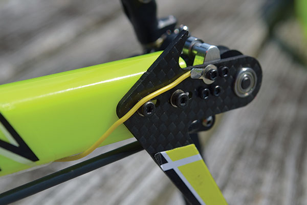
The antistatic wire was installed on the tailboom.
The tension from the belt also helps to hold the tailboom in place. This means that during a crash, if the tailboom doesn’t break, it can pull out from the main frames without damaging them. This brings me to the unique motor assembly. There is no main gear, no autorotation hub, and there are no pinions. There is a large-tooth wheel that attaches to one end of the motor to drive the tail belt, and the other end bolts to an aluminum main plate. The ESC is seated inside on the floor of the main frames before the motor and main plate are bolted into the main frames. The left and right belt tensioners are assembled, both of which ride on bearings, and are attached to the main frames. The cyclic servos are attached to their support assemblies and are bolted to the top of the aluminum main plate. Again, be careful not to strip any plastic.
Image
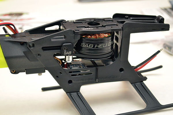
The motor installed in the main frames, with belt and tensioners in place.
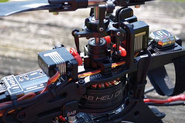
At this point, the rotor head is assembled. Each blade grip has its own set of bearings and thrust bearings, and the head spindle floats in rubber O-ring dampers in the head. There is a unique part called the bearing support assembly that consists of two bearings and a feeder. It is a keyed component that connects to the motor. The feeder damper keys to the motor shaft that drives the feeder. A setscrew attaches it to the bottom of the main shaft. The direct-style swashplate is much like the first-generation Goblin 700. The pitch links from the servos to the blade grips are not adjustable, and neither are the links from the servos to the swashplate. This should make setup simpler. With this last assembly finished, the build is almost complete. All that is left is to attach the rest of the electronics and take care of the wiring. If you’re like me, you will spend more time with the wiring than on the actual helicopter assembly! The plastic canopy is secured to the helicopter with magnets and a decal sheet is included. The flight battery is held under the front tongue of the main frames using Velcro and a strap. I installed my CGY750 controller on the back of the helicopter and mounted the sensor on the top of the front tongue. I had to level out the mounting plate for the sensor because the front tongue is angled slightly down. Using any kind of mini gyro would be ideal here, given the helicopter’s small size. Routing and tidying up the wiring wasn’t as bad as I expected, and there are places to install zip-ties and the included wire keepers. As an addendum to the manual, there is an antistatic wire kit for the tailboom. Some people say you will need it; others say you won’t. Erring on the side of caution, I installed the antistatic kit. This attaches a wire from the aluminum tail hub at one end of the tailboom to the aluminum main motor plate on the side frames. This prevents any potential static buildup from the belt from causing problems with your electronics. You could probably sit down in the morning and have this kit ready to fly later that day. Or you could, as I did, spread it out over a couple of evenings after work. The build time is short, but enjoyable.


Comments
Add new comment