Written by Terry Dunn.
Experience early English aircraft design with this laser-cut kit.
Flight video and photos by the author and Bryan McLarty.
As featured in the May 2015 issue of Model Aviation.
Specifications
Model type: Scale laser-cut kit Skill level: Intermediate builder; intermediate pilot Wingspan: 28.25 inches Wing area: 137.5 square inches Length: 19.13 inches Weight: 6.5 to 7 ounces Airfoil: Undercambered Needed to complete: Building supplies; four-channel radio and receiver; three sub-micro servos; 40-watt power system Street price: $85.98 for laser-cut kit; $110.98 for airplane kit plus faux Anzani engine kitTest-Model Details
Speed controller: E-flite 5-amp Pro Battery: Thunder Power 2S-325 mAh G8 Pro Force LiPo battery Radio system: Spektrum DX8 transmitter; Spektrum AR6310 receiver; three E-flite DS35 3.5-gram digital micro servos Ready-to-fly weight: 7.5 ounces Wing loading: 7.9 ounces per square foot Full throttle power: 5.9 amps; 40.4 watts; 86.2 watts per pound Flight duration: 6-plus minutesPluses
• Impressive scale accuracy. • Anzani engine looks fabulous. • Gentle park flyer manners.Minuses
• Some photos in the manual are too small to be useful, but larger photos can be viewed online. • Wing is challenging to frame without a jig.Review
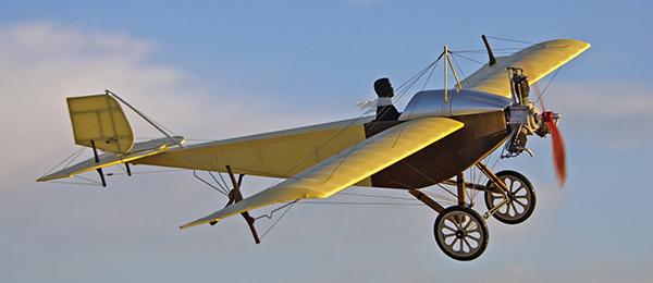
Modeling a pioneer-era aircraft often means tackling multiple wings, fragile structures, and a labyrinth of rigging wires. Although some modelers view those challenges as half the fun of such a project, the rest of us can’t see past the countless hours in the workshop. For builders in the latter group, the 1913 Eastbourne Monoplane presents a good alternative. It has classic pioneer-era looks, only one wing, and modest rigging wires. Perhaps that’s why so many modelers have recreated the Eastbourne throughout the years, although only one full-scale original was ever built. Retro RC’s rendition of the Eastbourne is a laser-cut kit intended to be an electric RC or CO2-powered Free Flight model. I built the review model for RC. Its 28.25-inch wingspan places it firmly in the park flyer category. Despite the model’s small size, it is surprisingly true to the original design. Retro RC suggests this kit for experienced builders, and I agree. It’s not that any aspect of the build is difficult, but it requires some skills that rookie builders may not yet have. For instance, you will have to do a fair amount of bending music wire parts to shape, as well as laminating wood strips. None of this is difficult, but you may find it overwhelming if you’re not already comfortable with basic construction techniques. The kit is packed in a plastic bag containing all of the laser-cut wood, metal stock, and various hardware needed for assembly. The color manual is clear and well thought out. Each step has a thumbnail photo to help guide the builder. In some cases, the photo is too small to be of any help. Retro RC has posted a PDF file of the manual online so larger photos can be accessed.Assembly
Standard hobby building tools are all that you need to assemble this kit. I used thin and medium CA adhesives for most of the assembly steps. The only exception was when I used carpenter’s glue to laminate basswood strips for the the rudder and horizontal stabilizer borders. Instead of reporting on each step of the build, I will touch on a few of the highlights. One thing that I like about the manual is that it has you cover the subassemblies as they are completed. For instance, the tail feathers are the first parts built and they are covered before work on the fuselage begins. Having a finished part on the workbench motivates me to keep the build moving. It also prevents a marathon covering session at the end of the build. The landing gear design is surprisingly accurate. Even the tail skid articulates similar to the full-scale airplane. The wheels are made of assembled wooden hubs with rubber O-ring tires. The overall effect is quite convincing. The open structure in the rear of the fuselage must be covered. I used Stevens AeroModel AeroLITE antique white covering in this area, as well as on the wing and tail surfaces. AeroLITE has quickly become my favorite iron-on covering. It is lightweight and shrinks well over compound curves. I applied brown craft paint as if it were a stain to the sheeted fuselage parts. I painted an area and then immediately wiped off the excess with a clean rag. This same technique was used on exposed wooden parts such as the wheel struts, tail skid, and control horns. The silver-looking areas of the fuselage were covered in AeroLITE and then painted with silver spray paint. I apparently built the fuselage with a slight twist from front to back. This became evident when I attempted to mount the horizontal stabilizer. When sitting flat on the rear part of the fuselage, the stabilizer was noticeably out of alignment with the wing-mounting tubes. I simply shimmed the stabilizer to rest level with the forward part of the fuselage and rigged the rudder to be perpendicular to the stabilizer. Most assembly steps for the Eastbourne do not require plans. The primary exception to this is the two-panel wing. A full-size drawing of one panel is provided to illustrate proper rib spacing. I found it somewhat difficult to get the wing started because the undercambered airfoil prevented either spar from resting flat on my workbench. As an alternate method, I skewered the ribs onto a 7.5mm-diameter carbon-fiber tube that I found in my shop (an arrow shaft, I believe). The tube was a snug fit in the holes cut in the rib profile. This setup held the ribs in position while I glued the spars and trailing edge into place. During wing assembly I must have let some CA wick down to the carbon-fiber tube. When I tried to remove it, it was stuck! Instead of potentially destroying the wing in an attempt to remove the tube, I left it in place and accepted the 0.3-ounce weight penalty. I had to remove the tube from the outer three ribs on each panel to allow the aileron pushrods to reach the necessary bellcranks. Even with the tube in place, the completed wing panels were lightweight and strong. Although the ailerons appear to use pull-pull cables for articulation, that system is a cosmetic scale feature. The actual control comes from pushrods that are connected to a single aileron servo in the fuselage. A carbon-fiber pushrod runs down each wing panel to the bellcranks. From there, music wire pushrods reach to the ailerons. A misprint on the plans states that the music wire pushrods are 5.25 inches long. They are actually approximately 2.75 inches long. I added a v-bend on these pushrods to allow for small length adjustments. I mistakenly jumped ahead of the manual and completed both carbon-fiber pushrods too early. I should not have set their final length until I had the wings in place. Consequently, my pushrods were roughly 3/16 inch too short. I compensated for this error by increasing the width of the block that connects the pushrods to the servo. When mounting the wing to the fuselage, be sure that both wing panels are at the same incidence. I noticed that mine were slightly off—perhaps another symptom of my fuselage twist—and required adjustment. This correction was easy to make and ensured that my model would fly true. Three miniscule E-flite DS35 3.5-gram digital servos sit side by side within the cockpit area. The servos are connected to a Spektrum AR6310 receiver. I placed 1/8-inch tall spacers below the aileron servo to raise it. This prevents any conflict between the aileron pushrods and the pull-pull cables used on the rudder and elevator. The kit includes fishing line for the cables as well as aluminum tube crimps. Despite their apparent complexity, I found the cables easy to configure. The manual calls for a 10-gram brushless motor but I decided to use a slightly larger, 14-gram E-flite Park 250 outrunner. The firewall had predrilled holes that fit the motor’s mounting pattern perfectly. I connected the motor to an E-flite 5-amp Pro ESC that is located below the battery tray. I have flown the Eastbourne with batteries ranging from 250 mAh to 430 mAh with weights of 16 to 29 grams respectively. My favorite battery is a Thunder Power 2S 325 mAh G8 Pro Force that weighs 25 grams. It provides a good combination of weight, performance, and duration. The battery fit improved after I enlarged the access hole in the battery compartment and relocated the magnets that secure the battery hatch. The power system pulls 5.9 amps and produces approximately 40 watts with a GWS 6 x 5 propeller, which I think is perfect for this airplane. The bright orange GWS propeller looked out of place on this model, so I gave it a faux wood finish by coloring it with a brown Sharpie marker. Before adding the rigging, I sprayed all of the covered areas of the model with a light coat of flat clear spray paint. This removed the shiny finish of the AeroLITE and gave the airplane a more authentic look. The completed model required 1/2 ounce of lead on the firewall for proper center of gravity. I sandwiched two 1/4 ounce lead slugs between the firewall and motor mount and then painted them brown to match. This brought the final weight to 7.5 ounces. Although the weight is more than the 6.5 ounces maximum shown in the manual, some of the weight difference can be attributed to my error with the tube in the wings. Despite being overweight, the wing loading and power loading values for the model were promising.Image

Retro RC’s kit for the 1913 Eastbourne Monoplane includes laser-cut parts and all of the hardware you will need.
Image
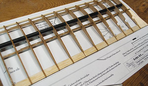
The wing is the only part of the Eastbourne that is built over the plans. The black carbon-fiber tube was used to assist with framing, but was accidentally glued into place.
Image

The lip of the battery bay was opened to accept a Thunder Power 325 mAh G8 Pro Force LiPo battery. E-flite 3.5-gram digital servos fit nicely in the stock cutouts.
Image


Comments
Add new comment