Written by Joe and Chris Hass
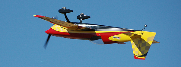
A 3-D aircraft with beautiful flight performance
Specifications
Model type: Scale Aerobatic 3-D Skill level: Advanced Wingspan: 103.5 inches Wing area: 130 dm2 Length: 102 inches Weight: 26 pounds, 2 ounces Power system: 80-120cc gas engine Radio: Five-plus-channel radio system Construction: All composite Covering/finish: Painted-in-mold finish; available in white base or several color schemes Price: $2,095 plus $225 for shipping in 48 statesTest-Model Details
Power system: Desert Aircraft DA-120 with stock muffler; Futaba BLS-157HV servos (two per aileron, two on rudder, one per elevator, one on throttle); magnetic Jeti DPS 40 dual electronic switch and Jeti SPS 20 single electronic switch; Castle Creations BEC Radio: JR 11X; JR R1222X 12-Channel PowerSafe receivers; two-cell 2,700 mAh LiPo receiver batteries Smoke system: Tejera Microsystems Engineering smoke pump; Smart Water bottle fuel and smoke tanks Propeller: Falcon Propellers 29 x 9 Other hardware and accessories: Hanger 9 pushrods; Du-Bro 3mm ball links; Du-Bro 4-inch Treaded Lightweight wheels; Ohio Superstar Products 35% tailwheel assembly Engine ignition power: Through receiver, to BEC, to the SPS 20 magnet switch, to an RCEXL Opto gas-engine ignition kill switch, to the ignition module. Tools used: Bondhus extra-long hex drivers, available from RJR Cool ToolsPluses
• Beautiful finish. • Phenomenal flight performance.Minuses
• No instructions. • Plywood pieces for fuel tank and rudder servo tray needed to be reglued.Review
The epitome of Scale Aerobatic flight is the large aircraft (30% or larger) that are flown in International Miniature Aerobatic Club (IMAC) and the Extreme Flight Championships (XFC). These aircraft are stunning on the ground, fantastic in the air, and can perform maneuvers that seem to defy the laws of gravity and many local ordinances. To compete at these levels requires a combination of low weight, extreme strength, and tremendous durability so you can be flight-ready all the time. The Krill Extra 330SC has a painted-in-mold finish and composite construction and puts those requirements together in a beautiful package. All of the control surfaces are hinged with a center pivot—no hinge gap. All surfaces are removable for transportation. The structure is amazingly rigid. This is in no way a beginner’s aircraft, both from its flight characteristics and in assembly techniques. The kit is only the airframe. Wheels, pushrods, ball links, etc., are all supplied by the builder. Pilots at this level have their own preferences as to what hardware he or she uses. Installing the servos in the wings and horizontal stabilizers, along with the related control linkages, is a great place to start. Hex-head servo mounting screws are best used in combination with the Bondhus long hex drivers to hold the screws on the tip of the wrench as you reach deep into the horizontal stabilizers and wings. The composite surface skins have basic cutouts that need to be enlarged to allow the servo arms to be fully exposed and ensure full travel. Carefully locate the position of the servo arms by placing them on the servos and measuring from the center of the surface. Cut the surface with a high-speed grinder using eye protection. Low-tack tape can establish straight lines as a guide for enlarging the slots. For the outer aileron servo, there is a hatch. Dual composite control horns are epoxied in to each control surface. Ball links and turnbuckles complete the servo installations. Make sure you tie any servo extensions so they don’t come apart in flight. Because the composite material can be abrasive with the vibrations of flight, shield or wrap all of the exposed wiring. The horizontal stabilizers are supported and held in place with a composite tube that must be drilled and tapped. Start by epoxying a hardwood dowel into each end of the stabilizer tube. Center the tube and drill a hole through the bottom stabilizer skin into the hardwood block that is built into each horizontal stabilizer. Continue drilling through the tube, but not through the upper surface of the stabilizer itself.Image
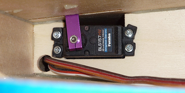
Elevator servos are installed inside the horizontal stabilizer.
Image
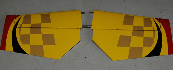
Horizontal stabilizers are joined with a composite tube and antirotation pins.
Image
The outer aileron servo is accessed with a hatch. Inner servos are accessed from the wing center in a similar fashion as the horizontal stabilizer.
Image
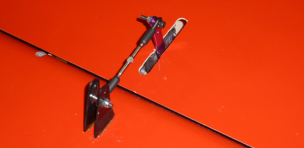
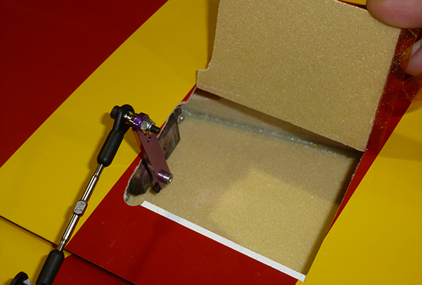
Note the dual control horns on the completed control linkage.
Insert the tube through the fuselage and insert the other stabilizer, making sure that both stabilizers are tightly seated against the fuselage. Drill a matching hole in the other horizontal stabilizer. Tap each hole in the stabilizers with a 4mm tap to complete the assembly. Set the wings, ailerons, horizontal stabilizer, and elevators aside. The engine dome is custom fitted to each fuselage. The custom fit is great, but it means that each aircraft is slightly different and that no template for engine centering is possible. The best way to solve this dilemma is to secure the fuselage vertically. Place the engine on the dome and mount the cowl. Place the spinner backplate on the engine then move the engine into the proper position so that the spinner matches the cowl. Carefully remove the cowl and mark the engine mounting-hole locations. It sounds cumbersome, but it results in a perfect fit. Aluminum spacers, 1/4 x 20 bolts, and blind nuts hold the engine securely in place. The throttle servo is located inside the dome with straight-line geometry to the throttle arm on the carburetor. The smoke pump is mounted on the outside of the dome on the bottom. The ignition module is mounted on a plywood plate with a combination of hook-and-loop fasteners and a hook-and-loop strap. This assembly is attached to the top inside of the dome. Rubber grommets on the top of the dome provide shock absorption for the module. Large grommets are used again on the side of the dome to allow the spark plug wires to exit the fuselage without abrading the fiberglass or shield. Rudder servos are ganged in line on the premolded servo tray—double check to make sure there is sufficient adhesive attaching the rudder servo tray. It is extremely important to adjust all servo throws so that there is matched throw in all directions. The same goes for the ailerons. We used multiple Hanger 9 amp meters to match the servos on each control surface. The receiver and satellites are mounted with foam tape in multiple directions throughout the fuselage. The removable tank floor contains molded areas for both a fuel and smoke tank. Again, double check to make sure there is sufficient adhesive on the tank floor mounts. To keep the airframe as clean as possible, Jeti magnetic switches were used for the ignition and radio system. A magnet is held above a spot on the top of the fuselage. A bright green LED light signifies that power is available.
Image
The inner aileron control servo inside of the wing.
Image
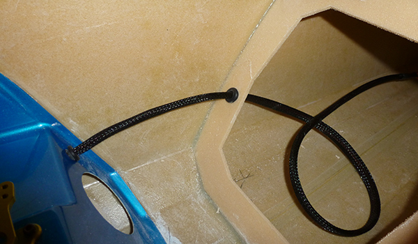
Use a flexible shield to protect the servo extensions.
Image
Beginning the installation of the ganged rudder servos.
Image
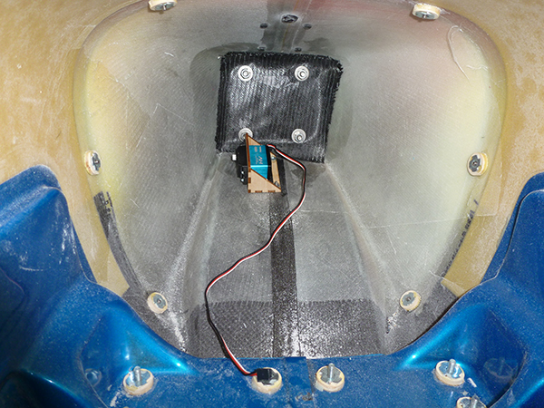
The throttle servo inside the engine dome.
Image
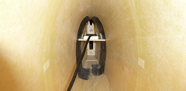
The cavernous tail section. Note the rudder cables and flexible covering over the elevator servo extensions.
Image
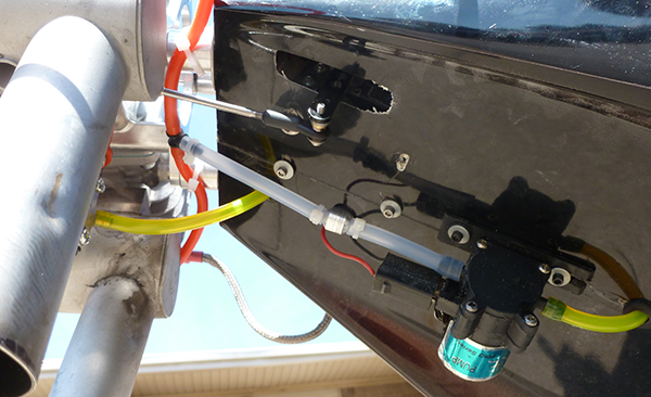
The engine installation. Grommets on spark plug wires prevent chaffing on the shield and fiberglass. The smoke pump is installed on the bottom of the engine dome.
Image
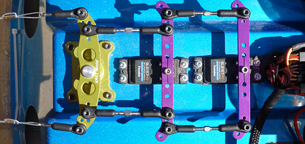
The completed rudder servo and linkage installation.
Image
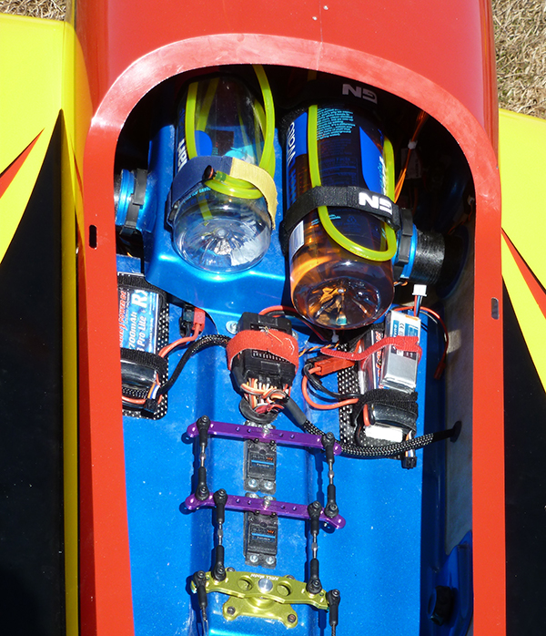
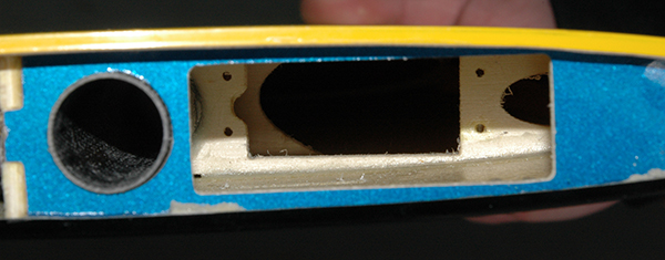
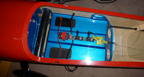
Fuel and smoke tank installation with system batteries.
Image
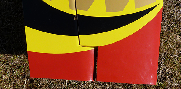
This shot of the wingtip shows how close the control surfaces are to the wing. The center of gravity is 1/4 inch ahead of the cutout for the aileron counterbalance.
Image
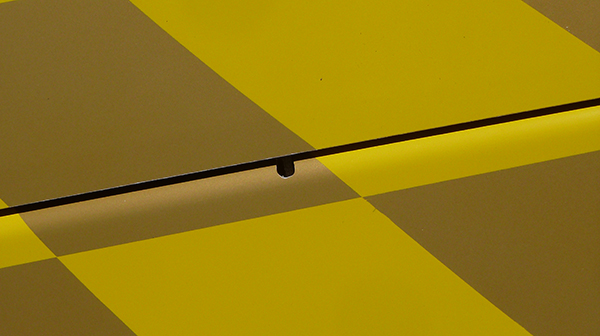
The molded control surfaces nestle inside the flying surfaces. The small cutout allows clearance for the hinges.
Because this is the competition aircraft Chris will use, he had the honors of making the first flight. This aircraft was different, right from the first takeoff roll. Chris describes it as “being locked in.” The model seems directly connected to the sticks on the transmitter. Because all of the electronics were used during the previous flying season, the difference can only be attributed to the airframe. This is probably because of the rigid construction (no flexing of the wings and the control surfaces). Chris explained that “control authority is maintained regardless of airspeed. Maneuvers are repeatable. Regardless of attitude or airspeed, the Krill Extra 330 does not hunt or drift.” All of this was accomplished without an onboard gyro. Let’s go through some maneuvers. The takeoff was solid with no tendency to veer off center, even with a direct crosswind. Climbout revealed the need for a little elevator trim. Loops tracked well, and rudder correction for crosswind was predictable and consistent throughout the varying airspeed of the loop. Knife-edge flight required just a touch of down-elevator. Four-point rolls were crisp with clear stops at each quarter, probably because the composite ailerons did not flex. Vertical lines showed the need for a little more right thrust, which was accomplished with a 1.5mm washer under the left-side engine mounts. Inverted flight required a touch of down-elevator, as expected. Stalls were straightforward with no tendency to fall off or snap. Spin entries were again solid, with a tendency to fall off until controls are given. Landing is as predictable as the rest of the flight—solid and in control through to touchdown. This is a very clean airframe that carries energy for a long time, so plan your pattern accordingly. The center of gravity is set 1/4 inch in front of the trailing edge of the aileron counter balance cutout at each wingtip. The term “you get what you pay for” comes to mind when discussing the level of prefabrication and flight performance. The extra cost of the airframe is well worth it in the air. There is never a wrinkle in plastic covering (there isn’t any covering!), and smoke oil is easily removed. You will enjoy your Krill Extra 330SC.
Image
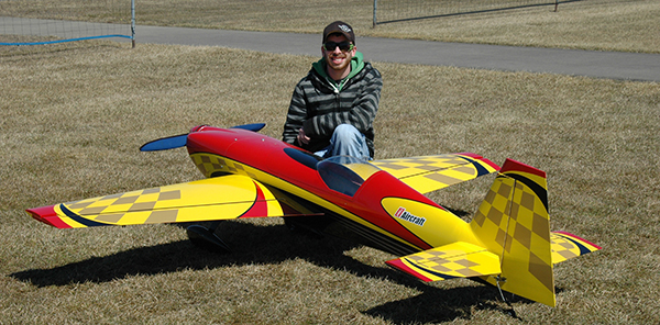
Ready for first flight, the pilot wears a confident smile.
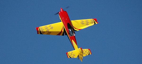
Image
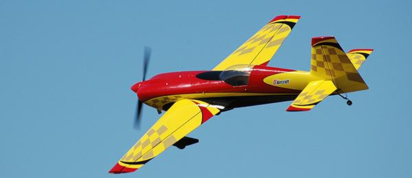
The Krill has rock-solid performance in inverted flight.
Image


Comments
Add new comment