
Part 1: Design, tail group, and fuselage
Image
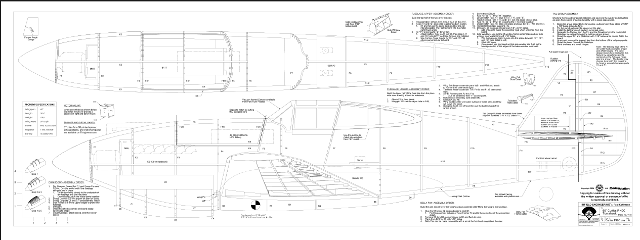
DOWNLOAD FREE PLANS!
Buy full plans online at plans.modelaircraft.org/product/curtiss-p-40c/Image
Document
Document
Document
Document
Document
Document
Document
Document
Image
Image
Image
At a Glance

Some P-40 History
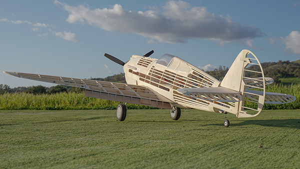
Like the P-36, Curtiss’ P-40 was quite a success story. Although it is often described as being obsolete at the beginning of the war, it was actually just entering service at the time of Pearl Harbor. The P-40 was extremely responsive over a wide range of speeds, dove like a bullet, and could take tremendous punishment. What it could not do was operate aggressively at high altitude like a Messerschmitt with its superior higher-boost supercharger, nor could it beat a lightweight opponent, such as a Zero, in a low-speed turning fight. Despite the P-40’s shortcomings, pilots who learned to leverage the P-40’s strengths were tough to beat and many became aces. Curtiss continually improved the P-40, with variants reaching all the way to the P-40R by 1945. Although steadily gaining in weight and power, all models except the P-40Q were readily identifiable as offshoots of that first P-40 that was converted from a P-36. Nearly 14,000 P-40s were produced throughout the course of the war and flew for two dozen nations.Building the P-40C
Because this model was derived directly from a P-36, it resembles a P-40A, B, or C model. There were a few obvious differences between these variants other than armament and the addition of a drop tank for the C. I plan to add a tank to the prototype at some point, so I’m calling my model a P-40C.Building the Tail Group
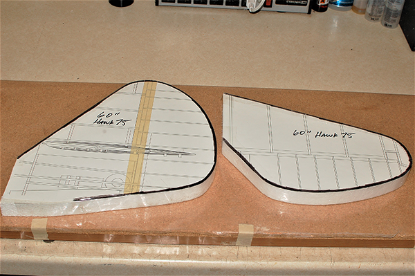
Construction of the tail group begins by laminating the outlines of these parts. Laminations are stronger than built-up balsa parts. Start by making a form for the fin/rudder and another for the horizontal stabilizer and elevator. Forms are often made from foam board or thin wood. Soak 1/2-inch wide strips of 1/16-inch balsa in water overnight or longer. Wrap the softened strips around the form. Use carpenter’s glue to adhere each successive layer to the previous one. After the outlines are fully cured, they can be pinned over the plans. Assemble the tail group inner framework parts in numerical order. Most of these parts have feet, so stand these parts on the board with the feet down.Image
Image
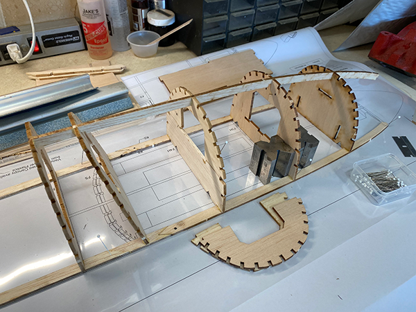
Building the Fuselage
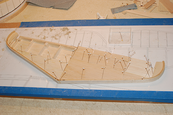
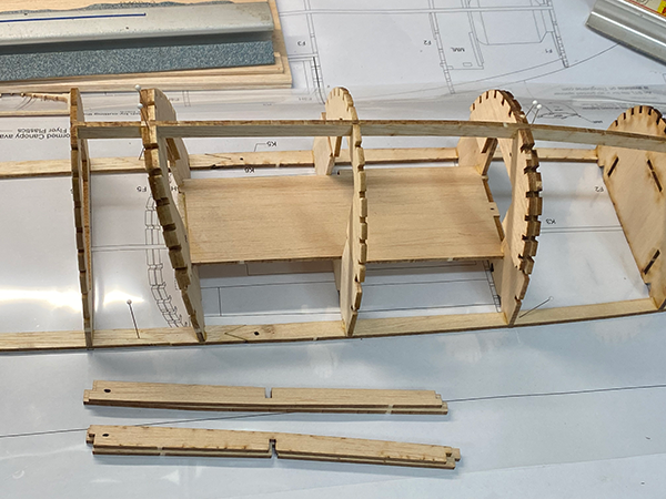
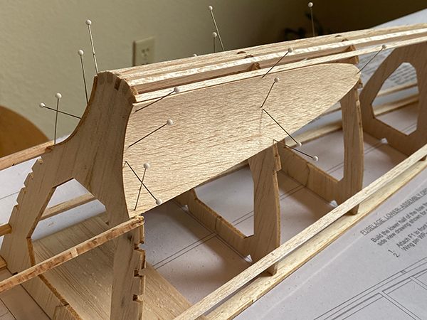
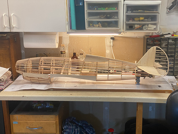
The upper half of the fuselage is built on top of the building board. Pin the horizontal keels to the board. Note that K1 is slightly longer than K2. When positioned in the correct spots, the fuselage opening will be aligned with the motor for right thrust and downthrust. Now add the upper former halves. Use the paper angle gauge to set the angle of the tilted formers that make the back of the battery hatch and the back wall of the cockpit. Tie the rear formers together with keel K3. Next on the list is the battery hatch opening. Assembling this hatch is simple if it is done as described here. First, glue the lower hatch rails K4 to formers F3T, F4T, and F5T. Now, prop hatch formers F3H, F4H, and F5H into their positions. Next, tie all of the forward formers together with keel K5, including the hatch formers. Slip the upper hatch rails into position from each side and glue them only to the hatch formers. It helps to put waxed paper between F3T/F3H and F5H/F5T to ensure that they don’t get glued together. After the fuselage is completely assembled, the hatch will be freed with a razor saw by cutting K5 between these former pairs. Install the side window panels next. Use the side view on the plans as a template to cut two 1/16-inch balsa panels slightly oversized to make the inner panels. Dampen the panels and glue them to Formers F7T through F9T. Now, add a few 3/32 × 1/8-inch stringers to keep the fuselage assembly true so that it can be removed from the board. After unpinning the upper fuselage, glue plywood former F1 to keels K1, K2, and K5. Assemble the tailwheel plate by gluing TW, F9B, and F10B together. Build the wing bolt boss by assembling parts WB1, WB2, and F6B. The drawings on the plans help explain these steps. Use epoxy for maximum strength in these critical areas. Now, all of the lower fuselage formers can be glued to their upper former mates. Glue each one at the same angle as the matching upper former. Tie formers F1 through F4B together with keel K7. Dampen the outer sides of wing saddles WS and glue them to F4B through F8B. Tie formers F8B through F11B together with keel K8. Now, add the rest of the stringers, alternating from side to side and top to bottom to avoid warps. The base fuselage construction is finished when the last stringer goes in.Building the P-40: Chin Scoop and Nose Fairings
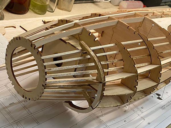
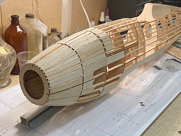
Our build will depart from the P-36/Hawk in earnest now as we add the large chin scoop. Start by dry-fitting scoop formers S2 through S4 to center scoop rail S1. Adjust the fit of these parts until this assembly mates closely to the underside of the fuselage assembly. Glue the chin scoop parts together.Image
Image
Image
Image
Image
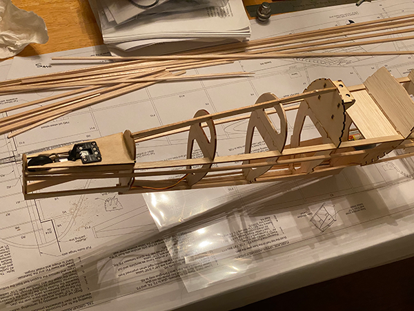
Until Next Time
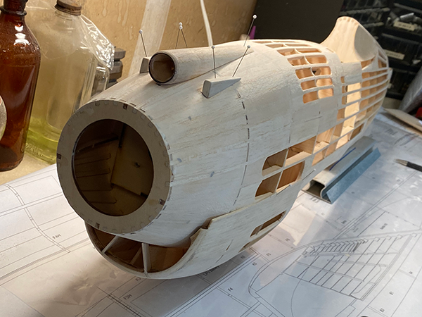
At this point, the nose and the tail group of the project are screaming P-40! This is a good time to set these parts aside and shift focus. Next month, we’ll tackle the wings and internal hardware. Until then, fly low and build light!SOURCES:
AMA Plans Service
(765) 287-1256, ext. 507
https://plans.modelaircraft.org
"Fighter Face-Off," Model Aviation, October 2018
www.ModelAviation.com/fighter-face-off
Manzano Laser Works
www.manzanolaser.com


Comments
Add new comment