
Written by Greyson Pritchett
Precision Aerobatics on a budget
Product review
As seen in the March 2017 issue of Model Aviation.
Bonus video
Specifications
Model type: Precision Aerobatics/Pattern Skill level: Intermediate Wingspan: 62 inches Weight: 5 to 6 pounds advertised Radio: Futaba 18MZ Construction: Balsa and light plywood Price: $399 Power system: Hacker A50-12S V3 14-pole; Castle Creations Talon 90 ESC Battery: Thunder Power 5S 4,000 to 5,000 mAh 25C LiPo Propeller: Falcon 16 x 10E carbon fiber Receiver: Futaba R7008SB Servos: Futaba S9650 Tested weight: 4.89 pounds Takeoff weight: 6.20 pounds Flight time: 6 to 8 minutesPluses
• Affordable. • Lightweight review model lighter than advertised. • Easy to assemble. • Easy to transport.Minus
• Only one color scheme.Product review
The 62-inch Acuity, designed by Andrew Jesky, is likely the best-flying Pattern aircraft for the money and size that you can find. I spent a full season flying an Osiris, another great Pattern airplane of similar size, also designed by Andrew. The Acuity seems to be the next-generation design. There will be two versions of this airplane—the one reviewed here, and a full two-meter that will be available in the spring of 2017. These models use balsa and light plywood construction and are still making weight at 11 pounds. It’s really exciting to see non-composite construction return! Now that I have that settled, I can get into the details of this great new aircraft. AJ Aircraft is a company that Andrew started with his brother, Joe, and father, Tim. Andrew works for Textron Systems in Utah and is the product designer for AJ Aircraft in Monroe, Michigan. He has been flying RC since he was 7 years old. Andrew is a seven-time RC Aerobatics Nats champion and winner of the 2011 and 2015 Tucson Aerobatic Shootout Invitationals. He has competed as a member of the F3A (RC Aerobatics) World Championship Team—placing second in 2007, third in 2011 and 2013, and fourth in 2015. He will again compete as part of Team USA in Argentina in the fall of 2017.Assembling the Model
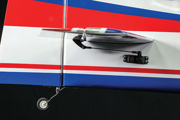
When you receive the Acuity, make sure everything is in the box and that you understand each component. Review each hardware bag. They are clearly marked indicating where they are to be used. I always leave them in the bag until I am ready to use them. Before assembling anything, check the security of all preinstalled hinges on every control surface. I’ve never found a loose one in an AJ Aircraft product, but there’s always a first time! When you have the airplane out of the box, you are ready to start a huge step that is also the first step that a lot of people do not do. Go over every wood-to-wood contact there is on the airplane with a fresh bottle of thin CA adhesive while you can get to them, with the cowl off as well as the landing gear. Determine the servo placement for the tail (pushrod for the servo in the rear or pull-pull for the servo up front). I was able to achieve proper center of gravity (CG) and found it much easier to put the rudder servo in the rear.Image

The servo and linkage with 90° setup. Take a little time with this and you’ll only need to use a small amount of subtrim.
When you make the covering cutouts on all components, use a covering iron to heat every edge, make the cuts with a fresh #11 blade, and then reheat every edge. While that iron is hot, go over every edge that will be hinged. You might need to reopen a couple with a #11 blade, but after the control surface is installed, there’s no fixing any loose covering, so do it now. The assembly will go fast if you take the time to identify subassemblies and have every component that you plan to use. For example, I like to install the control horns for ailerons, elevator, and rudder at the same time. (Use epoxy and chopped fiberglass for this—it’s lightweight, strong, and doesn’t run.) Every servo should be trial fitted and screw holes drilled with a pin vise, a servo-mounting screw placed in the hole and removed, and a drop of thin CA placed in each hole. Do all of the servo mounts at the same time. This saves a bunch of time! There are a couple of steps that are tricky for someone new to putting together a contemporary model as it’s currently built and delivered. One step might be the stabilizer installation. Start by sliding it into the stabilizer slot, and with a ruler, measure each side in the same place until the measurements are equal. Next, measure the length from side to side from the canopy clip to the outer edge of the stabilizer. I like to use the rear outer corner of the stabilizer. Adjust until that’s perfect and confirm the left and right measurements. Put the wing tube in and ensure that it is aligned in every possible way. I like to put the fuselage with the wing tube and the stabilizer in and align the assembly in this order: side to side, front to back, and up and down. If the stabilizer doesn’t line up perfectly with the wing tube (there are many ways to measure this, but if this assembly is up on a stand, trust your eyes!), your cool new airplane will always make you chase down trim problems if it is not correct.
Image
The stabilizer, elevator servo, and linkage layout.
You can easily see if one side of the stabilizer is “up” as compared with the wing tube. Gently sand the stabilizer opening on the bottom to lower the high side. You might have to go through this many times. I would not consider this a hard part, but I would think of it as a test of your patience. This part takes roughly an hour to two hours, depending on how many tries it takes you and whether or not you have done it before. When the stabilizer is correct and you’ve confirmed it numerous times, use thin CA glue on the top on both sides and then the bottom on both sides. There’s plenty of talk among modelers about removing the covering for this, but I’ve never removed it and never had a problem leaving the covering on the stabilizer inside of the fuselage. The stabilizer is the most critical step in the assembly. If you’re not in the mood, don’t do it. It has to be perfect. Next you need to mount the split elevators. You’ll notice that the composite connecting surface is preinstalled on one side. Sand this only enough to remove the shine and improve the glue surface. Lay these on a flat surface and ensure they are perfectly flat at the trailing edge. Confirm this by dry fitting the elevator halves on the stabilizer and constantly checking alignment. Make a small dot at each hinge location on the stabilizer with a Sharpie marker. The hinges are already in the elevator halves. Slide them together and gently insert them into the hinge slots, checking both elevator halves’ alignments up and down with each other and the surface contact alignment to the stabilizer. When you’re satisfied that this is perfect, mix together some epoxy and milled fiberglass. I like to put the adhesive onto the blank side on the balsa—not too much, just enough to cover the contact area. Slide them together behind the stabilizer, insert the elevator halves into the stabilizer hinge slots, and look for the dots you made on the stabilizer. Carefully put a drop of thin CA glue here, and the elevator halves will hold the epoxy joint together while it dries. When this is done right, your airplane will fly correctly.
Image

There is plenty of room inside of the fuselage, and battery placement is not an issue.
The easier part is installing the cowl. The big thing about the cowl is that you must get the mounting holes aligned perfectly. This, no doubt, helps with airflow through the back of the airplane, but it will look terrible if done incorrectly. Get a pencil and highlight the predrilled holes on the fuselage. Open each hole with a pin vise and a drill bit to the size of screw that you will be using to install the cowl. Run a screw in and out, add a drop of thin CA adhesive, and repeat running the screw in and out. When that’s complete, place 4 or 5 inches of blue masking tape over the hole and run it back toward the rudder. Mark where the hole is on the tape with your pencil. (I poke a hole in the tape.) Pull the tape back so that if you were to lay it back down it would be right on top of the predrilled hole for the cowl. Leave the tape down for now and put the motor on using the correct size standoffs. Trial fit the cowl over the motor and fit the cowl to the spinner backplate. Get that aligned so there is approximately 1/16 inch from the cowl to the backplate. When that looks correct and it’s good to go, remove the cowl, pull the tape back enough that the cowl will now be under the tape, lay the tape back down, and drill the hole exactly on the mark you made. I like to tape the cowl down securely and look it over one last time before drilling these holes. Finally, put the screw where you are going to use it, slightly into the cowl and the wood behind it, confirming the accuracy of your work. You can take the screw out if needed. It’s a good idea to carefully put a drop of thin CA glue into the cowl holes from the outside so the fiberglass doesn’t fray.
Image

The motor and ESC installation is easy and clean using the recommended power system.
Next is the hardware. The order for all hardware installation is bolt, washer, ball link, control horn, washer, and locknut. To be safe, put a drop of thin CA adhesive on the locknut to make sure that it won’t come off. If you are not comfortable with using CA, use a small amount of Loctite. The main reason for that is that if you get Loctite adhesive on the ball link, you can clean it off … but with CA that could be a different story. Following the subassembly approach, I like to install all of the hardware at the same time. Finally (you’re close!), look at these closing steps. I think they pretty much speak for themselves: • Plan your plumbing and use heat-shrink material on all of the extensions inside of the fuselage, and removable security clips on the aileron extensions. • Center the servos and make sure you have 90° from the servo horn to the control rod. • Mount the landing gear. It’s mostly been in the way until now. Be sure to use Loctite adhesive on these bolts. • Mount the ESC in the open space under the motor box; solder the bullets before installing. • Mount the propeller, spinner, and wings.
Flight
Before you test-fly anything, check the CG, then make one last CG check while you are test-flying. Pull up to a 45° angle and let off of the sticks. It should remain flying at that angle. After you do that, pull up to another 45° angle and roll inverted. Let go of the sticks and the nose should dip a little. If all of that is good, your CG is right on! When you land the Acuity after its first flight, immediately unplug the battery and check to make sure nothing is too hot. If all is good, be sure to mark your battery placement before removing the flight battery so you can have the same performance next time! I like to do this in light pencil for the first 15 to 20 flights, and when I’m convinced that the battery/CG is where I want it, I mark the battery placement with a Sharpie. After that is finished, always check all of the links and hardware to see if anything is coming loose. If something is going to break or go bad, it will likely happen early. You will want to do this after every flight for the first 10 to 20 flights, just to be safe rather than sorry. I also suggest a thorough preflight inspection each time you fly. Pull on the horns and linkage—basically check everything that could possibly loosen.Image


Comments
Add new comment