
A 2-meter glider kit
By Jerry Parks | [email protected]
Photos by Jerry Parks
As seen in the October 2023 issue of Model Aviation.
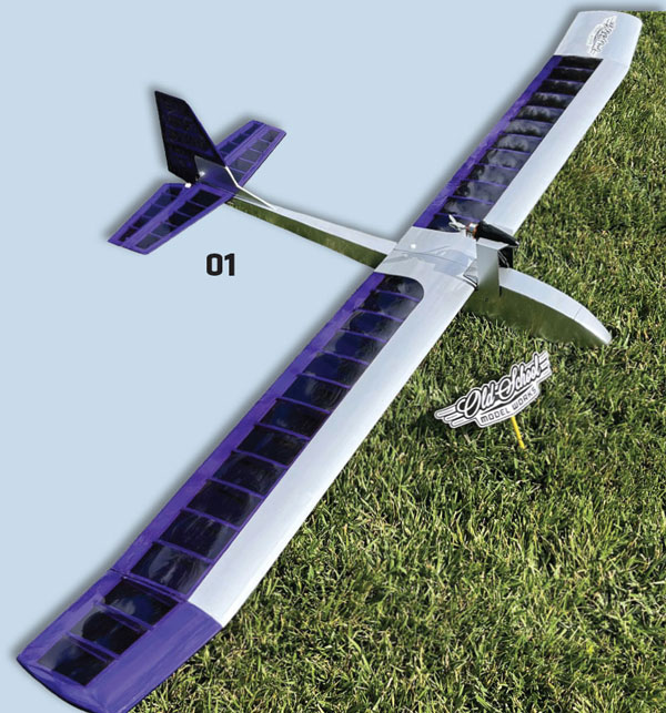
If you are considering adding a 2-meter glider to your hangar, the Old School Model Works Wayfarer might be a good fit. With a tried-and-true design, the Wayfarer is an easy flyer that lends itself to a low-stress, slow-things-down kind of day.
The robust fuselage and two-piece wing design make the glider easy to transport, and it’s a snap to assemble and disassemble at the field. With the electric power pod and a 3S LiPo battery, you can fly to your heart’s content with the help of some thermals.
This balsa wood kit was shipped from Old School Model Works via UPS and arrived in perfect condition. The box was wrapped in plain brown shipping paper—a nice, old-school touch.
Image

At a Glance
Image

Specifications
Type: Glider Wingspan: 79.5 inches Wing area: 560 sq. in. Airframe length: 37.25 inches Weight: 26 to 28 ounces Components needed to complete: Two- to three-channel radio system; two 40- to 70- inch-ounce mini servos; 2,200 mAh 3S LiPo battery; 2204/2206 brushless motor; 25-amp ESC; 5-inch propeller; two 24-inch pushrods; two rolls of covering Price: $149.95Pluses
- Price point, packaging, and shipping are good.
- High-quality materials and laser cutting are provided.
- Included hardware is of good quality.
- A well-thought-out manual with access to supplemental pictures and tips is included.
- Customer service is good.
Minuses
You need to supply your own pushrods, clevises, (and hi-start towhook if this option is used).Manufacturer/Distributer
Old School Model Works (513) 755-7494 www.oldschoolmodels.com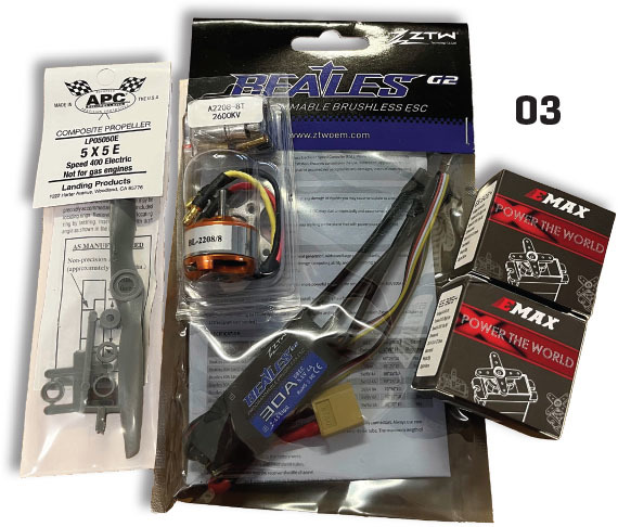
Getting Started
First, read the builder’s manual and familiarize yourself with the supplemental tips and build pictures offered through the Old School Model Works website. The manual includes a QR code that will conveniently take any smart device directly to the supplemental information. Next, perform an inventory of the included wood and hardware. Clean and prepare your work area and have your building tools and supplies ready to go. (Builder’s note: I recommend highlighting steps 6, 11, and 12. These steps require attention to the specific orientation of parts.) The manual starts with assembly of the right wing panel. Note that the manual has check boxes beside each step. The steps that require both left and right builds have two check boxes, making it easy to keep track of completed sections. Additionally, you will notice that the build pictures are quite detailed but are printed in a black and white, old-school fashion. This is when utilizing the QR code to view the build pictures in color is helpful. Again, I recommend highlighting step 6. Be mindful of the sheer web orientation before permanently gluing things in place. (Builder’s note: For step 8, work your way down the wing panel with the ribs and sheer webs. I chose to place each rib and sheer web into position, squaring them with a machine square, and then tack-gluing them into place. This will make squaring them more efficient. It also allows you to adjust the web cutouts, if necessary, to center the corresponding cutout on top of the capstrip.) (Builder’s note: As referenced in the manual, ribs 1 and 2 can easily break when separating them from the parts tree. I found this to be unavoidable, but they fit into the wing assembly as two pieces and, once glued, were solid and secure.) In step 13, the aluminum tube that accepts the wing spar might require trimming. Be sure to test-fit the tube so that trimming can be done before you epoxy it into place. Steps 18 through 21 involve sheeting the wing panel. Follow the manual and the supplemental tips. Take your time and use wood glue. (Builder’s note: Step 21 will require some sanding for a proper fit.) Moving on to the tip panel, the build mimics that of the center panel. Again, be mindful of the sheer web placement and orientation. I continued the same method mentioned in the builder’s note for step 8. After removing the right tip and right center panel from the work surface, the manual would have you join and glue them together. I recommend that you complete the left center and left tip panel before joining; this allows you to make any adjustments necessary to have both polyhedral measurements the same. Step 33 will has prepare your work surface for building the horizontal/elevator and vertical/rudder. This part of the build is very straightforward; however, taking your time with the selection of wood and making exact cuts will pay off. (Builder’s note: Before you remove the tail sections from the work surface, place a mark on the hinge surfaces that match the planned hinge locations. After removing the sections from the plans, I like to cut the hinge slots and test-fit the control surfaces before sanding. It is easier to center the hinge slots with square edges.)The Fuselage
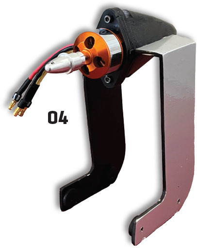
Build the fuselage on a flat bench surface. It does not require placing plans underneath; however, I like to have the plans on the work surface for reference. Having the plans under this part of the build also helps determine the needed pushrod length and servo orientation. The fuselage build seems simple, and the parts fit together very well. With that being said, as mentioned by the manufacturer in the manual, "building these parts square is key!" (Builder’s note: Take your time with the fuselage. Figure out a way to build the crutches square. The rest of the fuselage assembly requires those first steps to be very accurate.) The rest of the fuselage build I did per the manual specifications, and I had great success. When finalizing the fuselage build, you will be prepping the power pod T-nuts, sandwiching the nose cone balsa pieces together, and mounting the vertical stabilizer. Now is a great time to test-fit your pushrod tubes and plan the pushrod installation for after you have completed sanding and covering the model. (Builder’s note: The top hatch cover will require some sanding and trial-fitting as you go. Drilling and tapping a hole for the nylon thumb screw that holds down the hatch will be good practice because the same process is used to tap the wing hold-down bolt holes. I like to complete all parts of the build, and then do any test-fitting that is required before sanding and covering. This gives you a chance to make any adjustments for a squared-up fit and allows you to better plan how much sanding and shaping will be required.) In steps 66 and 67, you will test-fit the horizontal stabilizer to the fuselage. To do this, you will be directed to cut the aft slot of the vertical stabilizer. Be aware that once you have removed that piece of balsa from the vertical fin, it becomes susceptible to breakage before final gluing takes place. Again, taking your time in prefitting and shaping the balsa pieces will give you a great finished product. When you are satisfied with the fit of the horizontal stabilizer, the manual would have you mount it to the vertical stabilizer and fuselage. I chose to do the final sanding and covering before gluing the horizontal stabilizer in place.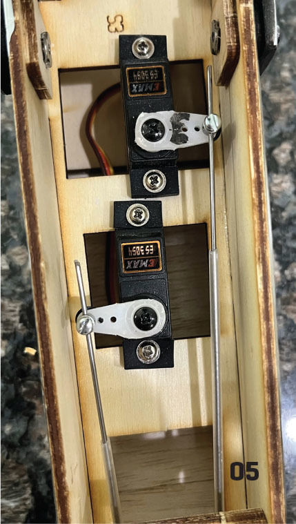
Joining the Wing Halves
Steps 69 to 72 involve joining the wing halves, which requires using the supplied 3/16-inch metal-wire spar. The manual has already instructed you to make a bend to the wire as designated on the build plans. The bend gives the center wing sections a dihedral angle. I found that the spar fits perfectly into the aluminum tube; however, it does require the bend in the spar to be perfectly centered up and down to allow the halves to join flush together.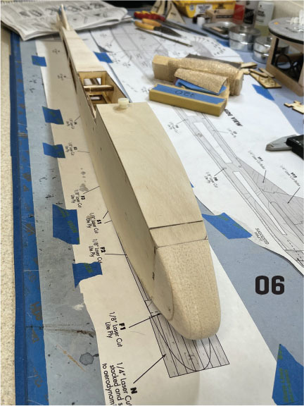


Comments
Add new comment