


Build U/Tronics Single-Channel Units

Written by Clancy C. Arnold Single-Channel Unit Part One Featured in the Model Aviation June 2015
I have decided that my designs should be documented to allow others to build my U/Tronics Control (U/T) units. I will start with the single-channel unit with the multichannel (4 to 7) encoder and decoder units to follow. I coined the name U/Tronics Control in 1982. U/Tronics Control stands for U/Control with electronics added. All U/T Control units are designed for use with standard, not digital, servos. To verify the accuracy of these instructions, I asked Mike Boucher if he would build a set of units if I supplied all of the material. Mike agreed and after each unit was built he shipped it to me for testing. All three of the units that Mike built worked right out of the box. I want to thank Mike for taking on this project. I also want to thank Mike’s wife, Robin, and his daughter, Rachael, and my wife, Pat, who has put up with my hobbies for 54 years. The typical use of a U/T single-channel unit is for throttle control for your CL model without going to a three-line control system. It even works if the insulated lines are slack! They can be used in CL Scale, CL Navy Carrier, and CL sport flying. When teaching a new or returning flier, if the person gets dizzy, you can slow the plane or cut the engine completely and land. It is fun to do multiple touch-and-gos in a single flight. The U/T single-channel unit is controlled by varying the resistance between the brown and green wires with zero ohms giving an output pulse width of 0.9 milliseconds every 20 milliseconds and 10K ohms giving an output pulse width of 2.1 milliseconds every 20 milliseconds. This will control nearly any analog servo or ESC.
Assembly
Study the pictures while reading the instructions. I have 60 years in electronics, so I will try to not leave any “obvious” steps out.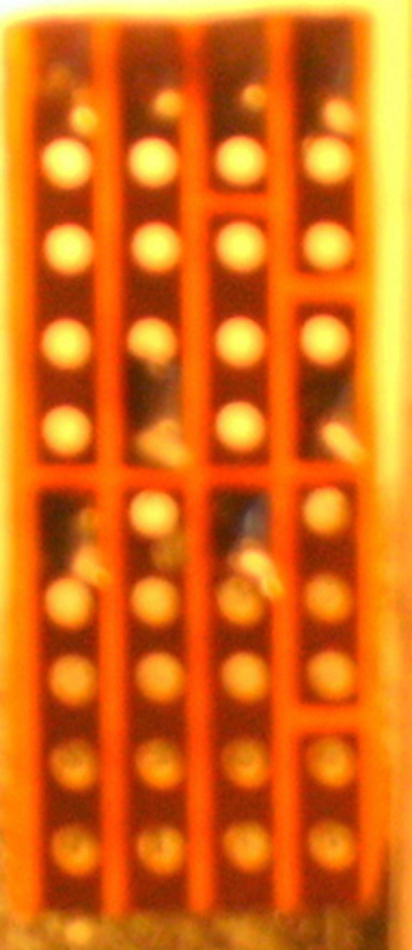
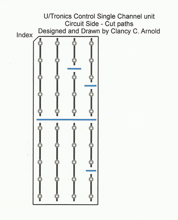
Single-channel circuit board circuit (copper) side, four paths with 10 holes each. The paths are cut in seven places.
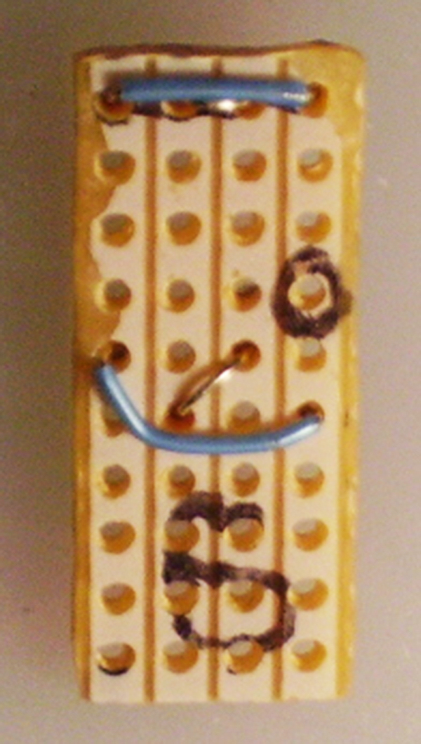
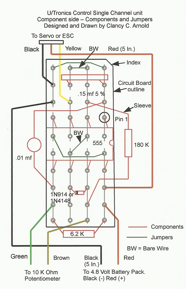
The component side of the single-channel circuit board with jumpers installed.
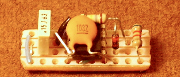
The component side of the single-channel circuit board with its components installed.
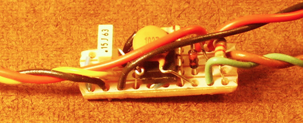
The component side of the single-channel circuit board with wires installed.
A single-channel unit with its circuit side showing.
The component side is shown on this single-channel unit.
Saw the board from the prototyping perf board material. Make sure the saw teeth are cutting from the circuit (copper) side first. If you cut from the component side, you might pull the copper paths from the board. I cut the boards by sawing through the next set of holes and then filing the edges smooth. You can make seven boards at a time from the 35 paths across the prototyping perf board material. Select and bevel one corner as shown in Drawing 1. This will give you an index mark to know which end is up when you turn the board over. You can put paint or tape on the corner to serve as the index marker. Following Drawing 1, cut the copper paths in seven places. There is .060 inch of space between holes, so try to remove .015 to .020 inch of copper centered between the holes. I use a sharp #11 blade and pull it firmly twice across the path in two places and then use the point to pick the copper off the board between the cuts. Using a permanent marker, mark the location for Pin 1 of the 555 Timer IC on the component side of the board at the hole indicated in Drawing 2. Visually inspect the board to verify that the paths are completely cut and a gap exists between the ends of the cut paths. The best way is to hold the board up with the circuit side toward you in front of a strong light source as in Picture 1. Note that all jumpers, components, and wires are inserted from the component side and soldered on the circuit side of the board. Always wipe the old solder off of the soldering iron’s tip before soldering each wire or component. I use a damp cellulose sponge. Do not exceed 10 seconds on any one solder joint! Cut to length, form, install, and solder two bare wire jumpers as shown in Picture 2 and Drawing 2. After soldering each component or wire, trim the excess length flush with the solder on the circuit side of the board (see Picture 2). Cut to length two insulated solid copper-wire jumpers, strip both ends 1/4 inch, form, install, and solder as in Picture 2 and Drawing 2. Form the insulated wires around, not across, the bare wires. Warning: Just before handling any integrated circuit (IC) or transistor, always touch a grounded piece of metal to reduce the chance of static electricity damaging the IC or transistor. Proper IC orientation is determined by the location of the indexing notch in the end of its case, which is at the pin 1 end of the package. Insert the 555 timer IC on the component side of the board with pin 1 in the proper hole. Start one row of pins in their proper holes then using the back side of an X-Acto knife blade, press the other row of pins inward to allow them to enter the correct row of holes. The spring tension in the pins will hold the IC in position for soldering. Visually verify that the pins are in the correct holes and that the IC is down against the board or wires that pass under the IC. Solder the IC pins on the circuit side of the board and visually inspect the board for solder bridges between paths. Form the leads for each component as shown in Picture 3 and install and solder per Drawing. 2. Install the 1N4148 or 1N914 diode with the black band located as indicated on the Drawing 2 and solder. Cut a 1/4-inch length of heat-shrink sleeve and slide it over one lead of the 180K ohm resistor and against the body of the resistor. Make two bends in the sleeved lead as in the pictures. Make one bend in the other lead and install the resistor in its holes as in Drawing 2 and solder. Form the leads of the .01 mF capacitor per the pictures. Install per Drawing 2 and solder. Form the leads of the 6.2 K ohm resistor according to the pictures, install it as shown in Drawing 2, and solder. Install the .15 mF capacitor per Drawing 2 and solder. Cut to length, strip, and tin 3/16-inch of one end of the following wires:
- Black No. 24: 5 inches
- Black No. 24: 4 inches
- Red No. 24: 5 inches
- Red No. 24: 4 inches
- Brown No. 26: 4 inches
- Green No. 26: 4 inches
- Yellow No. 26: 4 inches
Test Time
Temporarily tack-solder the brown and green wires to a 10K ohm potentiometer. Connect and solder the red and black wires to a mating connector for a 4.8-volt battery pack and plug it in. If there is no smoke, plug in an analog servo and see if it follows the potentiometer. The control signal for the servo is on the yellow wire. If the servo cable colors are black, red, and white, the white wire mates to the yellow wire. If the servo cable colors are brown, red, and orange, the orange wire mates to the yellow wire. If the servo does not follow the potentiometer, verify that the servo is plugged in correctly. If the servo is plugged in correctly, again visually inspect the board for solder bridges between paths and that all components are properly soldered to the circuit board and look for shorts between component leads on the component side of the board. After you have it working properly, coat the unit with two coats of Plasti Dip for tool handles. When you buy the Plasti Dip, shake the can. It should slosh around in the can. If it does not then it is probably expired. After opening a can of Plasti Dip, reseal it with a piece of aluminum foil covering the top of the can and extending part way down the sides. Secure it with the provided plastic lid. The plastic lid alone will not prevent the solvent from escaping. The finished unit should weigh approximately 8 grams. When you are finished watching it operate, unsolder the green and brown wires from the 10K ohm potentiometer. Install the U/T single-channel unit in your model with a servo to control the throttle on your engine and a 4.8-volt battery pack. If the battery is located inside your model, be sure to provide a charging jack wired between the on/off switch and the battery. Connect and solder the green and brown wires to a two-conductor connector. Add a mating connector to your insulated flying lines. Mount the 10K potentiometer on your handle and wire and solder it to a two-conductor connector. Add a mating connector to your insulated flying lines. I use 2.5mm miniature headphone jacks and plugs.Caution
If you plan to use the unit in an electric-powered model with an ESC mount, put the single-channel unit in a box inside the handle and connect the red and black wires to a 4.8-volt battery. Connect the yellow and black wires of the servo connector to your flying lines, and at the model to the ESC signal and ground. Connect the two outside pins. Instructions for building the multichannel encoder units can be found at www.ModelAviation.com/utronicsencoder and multichannel decoder units can be found at www.ModelAviation.com/utronicsdecoder. Welcome to the world of U/Tronics Control!Bill of Materials
One each is required and all parts are available on eBay.- Prototyping perf board, 0.4 x 1.0 inch (four paths of 10 holes each)
- 555 Timer IC, eight pin dip package
- 1N4148 or 1N914 switching diode (red glass w/black band)
- 180K ohm 5% 1/4-watt resistor (brown, gray, yellow)
- 6.2K ohm 5% 1/4-watt resistor (blue, red, red)
- .01 mF disc ceramic capacitor (103Z)
- .15 mF 5% stable base Mylar capacitor, 0.2 inch lead spacing (rectangle)
- 6 inches, #26 gage solid insulated wire, for jumpers
- 9 inches, red and black #24 gage insulated wire
- 4 inches, brown, green, and yellow #24 or #26 gage insulated wire
- Three-pin header, cut from 40-pin header (servo connector)
- 10K ohm potentiometer (rotary or slide)
- 1/4 inch of 1/16-inch heat-shrink sleeve material
- 11/8 inch of 3/16-inch heat-shrink sleeve material
Read Parts Two and Three


This Month's Issue

Join the AMA
![]()


5 comments
decoder
U/Tronics build
U/Tronics
Nice article. Yes, the 555
this is clearer than the
Add new comment