Written by Barry Yarkon
Digital exclusive review.
This review covers the Thunder Tiger Yak 54 3D Brushless ARF from assembly through its maiden flights.
About the author: A member/webmaster of the Rockland County Radio Control Club (RCRCC) and the Hudson Valley Radio Control Club (HVRCC), both in New York, Barry Yarkon is a previous contributor to Sport Aviator and ModelAviation.com.
Can a relative newcomer successfully step up to a frisky, 3-D-capable model such as the 45-inch Thunder Tiger Yak 54? How about after first assembling and flying a basic trainer, then an advanced trainer?
This review covers the Thunder Tiger Yak 54 3D Brushless ARF from assembly through its maiden flights. In Part Two, I will take the sticks and see how this works out!
This review continues the premise of two earlier reviews I wrote:
1. Basic Trainers: Thunder Tiger Trainer 40 OBL GP/EP/ARF
2. Advanced Trainers: Shulman Aviation Super Cessna ARF
For those two reviews, I collaborated closely with two very skilled RC fliers and modelers, Richard Landis (who also has a great deal of experience with electric power systems) and Daniel Landis (one of the top-rated F3A [Pattern] competitors in the USA). I was the designated “beginner.”
 I first built the Thunder Tiger Trainer 40 OBL GP/EP ARF (Photo above), a typical electric-powered basic trainer (high-wing, dihedral, flat-bottomed airfoil); I began to re-learn how to properly get started flying RC airplanes (see that review to learn why this was and what lessons were learned).
 With that under my belt, I built and reviewed a more sophisticated trainer from Shulman Aviation, the Super Cessna (Photo above), which is an electric-powered, high-wing, semi-scale design classified as an advanced trainer because of its symmetrical wing and lack of dihedral. That assembly was a bit more complex with a pull-pull rudder system.
Now, for this review, I took another step up in level-of-difficulty with the 45-inch Thunder Tiger Yak 54 3D ARF, a fully symmetrical, low-wing aerobatic Sport design. In Part One I’ll talk about the assembly, all the way through the maiden flights made by both Dan Landis and Frank Granelli at a recent local model air show.
Then, in a follow-up to this review, Part Two will contain an overall summary and discussion of my experiences, insights, and findings among the increasing capability levels of these three airplanes, and their impact on my modeling and flying skills.
The Plan
The underlying motive for this series of reviews was to see how successfully an adult beginner could advance his RC aeromodeling skills by assembling and flying three increasingly capable models. By the way, at this writing, all three aircraft are intact and in flying condition. The first two have each had minor repairs (with Richard Landis’ help), after some mishaps along my learning curve; more about that in Part Two.
This has been an interesting experience and certainly has accelerated my knowledge of assembling an ARF (Almost Ready to Fly), of LiPo batteries and electrical power systems, and the mechanics of flight. I also benefitted from the feedback of several members of the two local flying clubs that I joined along the way.
About Thunder Tiger Group and Great Planes
In September 2010 Aling Lai, chairman of the Thunder Tiger Group (Taiwan), announced that Hobbico, Inc. had been granted the exclusive rights to distribute Thunder Tiger products in North and South America. Thunder Tiger products are now available to hobby retailers through Great Planes Model Distributors and online through Tower Hobbies.
About the Full-Scale Yak 54
The full-scale Yak 54 is a 1993 Russian aerobatic and sports competition aircraft designed by Drach and Popov of the Yak-Aviation Corporation, formerly the A.S. Yakovlev Design Bureau JSC.
If you read the aeromodeling magazines, follow online forums, look at photos, or watch videos of the various competitions and club fun flies, there is a very large representation of RC model Yak 54s and 55s. A person would have thought that the full-scale Yak 54 was equally well-represented in airshows and general aviation—interestingly, that is not the case. It seems that the Russian manufacturer only made about a dozen of them.
The single full-scale Yak 54 that is flying in this country today is Jim Bourke’s Extreme Aerosports “Russian Thunder.” See www.RussianThunder.com.
About the TT Yak 54 3D Brushless ARF
Why did I pick this particular model to assemble? I was craving a “third airplane,” one that was electrically powered and small enough to fit in an average car trunk with the wings on.
One evening I received an email ad from Tower Hobbies announcing this model. It was handsome, electric and small; it seemed to fit my wish list, although I realized it would be quite a stretch for my flying skill. By the way, it is a coincidence that my first review model (the OBL Trainer) and this one both happen to be Thunder Tiger products.
So I did a little research. I found that Thunder Tiger Corporation’s Yak 54 product line is very deep. There are numerous models on their website (www.tiger.com.tw): from 45- and 55-inch wingspan (Sport Scale), to 30% (87-inch wingspan), to 33%, 35%, and 37.5%, up to a 40% (129-inch wingspan), which is in their premium TOC Series.
The model to be reviewed here is the “little brother,” the 45-inch Thunder Tiger Yak 54 3D Brushless ARF, a Sport Scale model in a slightly smaller version than the 55-inch model. A 45-inch wingspan is about 14% scale, based on the specs of Jim Bourke’s “Russian Thunder.” This is a highly prefabricated ARF marketed for intermediate pilots and above because it is designed to perform any aerobatic or 3-D maneuver in the book, as you will see.
With that under my belt, I built and reviewed a more sophisticated trainer from Shulman Aviation, the Super Cessna (Photo above), which is an electric-powered, high-wing, semi-scale design classified as an advanced trainer because of its symmetrical wing and lack of dihedral. That assembly was a bit more complex with a pull-pull rudder system.
Now, for this review, I took another step up in level-of-difficulty with the 45-inch Thunder Tiger Yak 54 3D ARF, a fully symmetrical, low-wing aerobatic Sport design. In Part One I’ll talk about the assembly, all the way through the maiden flights made by both Dan Landis and Frank Granelli at a recent local model air show.
Then, in a follow-up to this review, Part Two will contain an overall summary and discussion of my experiences, insights, and findings among the increasing capability levels of these three airplanes, and their impact on my modeling and flying skills.
The Plan
The underlying motive for this series of reviews was to see how successfully an adult beginner could advance his RC aeromodeling skills by assembling and flying three increasingly capable models. By the way, at this writing, all three aircraft are intact and in flying condition. The first two have each had minor repairs (with Richard Landis’ help), after some mishaps along my learning curve; more about that in Part Two.
This has been an interesting experience and certainly has accelerated my knowledge of assembling an ARF (Almost Ready to Fly), of LiPo batteries and electrical power systems, and the mechanics of flight. I also benefitted from the feedback of several members of the two local flying clubs that I joined along the way.
About Thunder Tiger Group and Great Planes
In September 2010 Aling Lai, chairman of the Thunder Tiger Group (Taiwan), announced that Hobbico, Inc. had been granted the exclusive rights to distribute Thunder Tiger products in North and South America. Thunder Tiger products are now available to hobby retailers through Great Planes Model Distributors and online through Tower Hobbies.
About the Full-Scale Yak 54
The full-scale Yak 54 is a 1993 Russian aerobatic and sports competition aircraft designed by Drach and Popov of the Yak-Aviation Corporation, formerly the A.S. Yakovlev Design Bureau JSC.
If you read the aeromodeling magazines, follow online forums, look at photos, or watch videos of the various competitions and club fun flies, there is a very large representation of RC model Yak 54s and 55s. A person would have thought that the full-scale Yak 54 was equally well-represented in airshows and general aviation—interestingly, that is not the case. It seems that the Russian manufacturer only made about a dozen of them.
The single full-scale Yak 54 that is flying in this country today is Jim Bourke’s Extreme Aerosports “Russian Thunder.” See www.RussianThunder.com.
About the TT Yak 54 3D Brushless ARF
Why did I pick this particular model to assemble? I was craving a “third airplane,” one that was electrically powered and small enough to fit in an average car trunk with the wings on.
One evening I received an email ad from Tower Hobbies announcing this model. It was handsome, electric and small; it seemed to fit my wish list, although I realized it would be quite a stretch for my flying skill. By the way, it is a coincidence that my first review model (the OBL Trainer) and this one both happen to be Thunder Tiger products.
So I did a little research. I found that Thunder Tiger Corporation’s Yak 54 product line is very deep. There are numerous models on their website (www.tiger.com.tw): from 45- and 55-inch wingspan (Sport Scale), to 30% (87-inch wingspan), to 33%, 35%, and 37.5%, up to a 40% (129-inch wingspan), which is in their premium TOC Series.
The model to be reviewed here is the “little brother,” the 45-inch Thunder Tiger Yak 54 3D Brushless ARF, a Sport Scale model in a slightly smaller version than the 55-inch model. A 45-inch wingspan is about 14% scale, based on the specs of Jim Bourke’s “Russian Thunder.” This is a highly prefabricated ARF marketed for intermediate pilots and above because it is designed to perform any aerobatic or 3-D maneuver in the book, as you will see.

 The Yak 54’s lightweight airframe surprised me. It came together at 1.98 pounds (31.6 ounces) without the flight battery. It is built up of laser-cut balsa and lite plywood with carbon-fiber landing gear and wing tube, and fiberglass wheel pants and cowl. Since weight is a premium in high-performance designs, compared to my prior basic and advanced trainers there is little sheeting and much more use of longeron construction. (See Photos above.)
This Yak 54 is available in two structurally identical models with slightly different Oracover color schemes: 4349-K20-03 is Red/White/Silver/Black; 4349-K21-04 is Red/White/Yellow/Black. Both are visually striking schemes and well-crafted, but more fragile than my other models, particularly around the hatch area of the fuselage. I’ve received a lot of compliments at the field on my “silver.”
The Yak 54 is exclusively for electric power. It is offered bundled with the recommended Ripper OBL-36/09-30A brushless outrunner motor. You add an ESC (electronic speed control) and four microservos and a propeller. I used an ElectriFly SS45 45A ESC provided by Great Planes, which has a built-in BEC (battery elimination circuit) suitable for a 3S1P flight pack.
I also chose to use four Futaba S3156 micro digital servos which are 3 pole ball-bearing units with metal gears and high torque, and an APC 13 x 4E propeller to begin with. Thunder Tiger recommends stepping up to a 12 x 6E propeller for 3-D, but our test flights showed that, in the right hands, 3-D is possible with a 13 x 4E. Two 12-inch servo extensions and a Y-connector are also needed. That’s it. Besides a few tools and adhesives, everything else is in the box. Of course, you supply the receiver, transmitter and flight battery.
The Yak 54’s lightweight airframe surprised me. It came together at 1.98 pounds (31.6 ounces) without the flight battery. It is built up of laser-cut balsa and lite plywood with carbon-fiber landing gear and wing tube, and fiberglass wheel pants and cowl. Since weight is a premium in high-performance designs, compared to my prior basic and advanced trainers there is little sheeting and much more use of longeron construction. (See Photos above.)
This Yak 54 is available in two structurally identical models with slightly different Oracover color schemes: 4349-K20-03 is Red/White/Silver/Black; 4349-K21-04 is Red/White/Yellow/Black. Both are visually striking schemes and well-crafted, but more fragile than my other models, particularly around the hatch area of the fuselage. I’ve received a lot of compliments at the field on my “silver.”
The Yak 54 is exclusively for electric power. It is offered bundled with the recommended Ripper OBL-36/09-30A brushless outrunner motor. You add an ESC (electronic speed control) and four microservos and a propeller. I used an ElectriFly SS45 45A ESC provided by Great Planes, which has a built-in BEC (battery elimination circuit) suitable for a 3S1P flight pack.
I also chose to use four Futaba S3156 micro digital servos which are 3 pole ball-bearing units with metal gears and high torque, and an APC 13 x 4E propeller to begin with. Thunder Tiger recommends stepping up to a 12 x 6E propeller for 3-D, but our test flights showed that, in the right hands, 3-D is possible with a 13 x 4E. Two 12-inch servo extensions and a Y-connector are also needed. That’s it. Besides a few tools and adhesives, everything else is in the box. Of course, you supply the receiver, transmitter and flight battery.
 The Thunder Tiger Yak 54 3D Brushless ARF came packed in an outer shipping carton which protected an attractive, sturdy two-level box with all of the parts bagged, partitioned, and securely packed. (See Photos above.)

 This is the standard to which most kit manufacturers aspire. It is especially important to get your airplane safely from factory, to distributor, to the store or warehouse, and through the common carriers such as UPS. The Yak 54 arrived with no damages.
 Photo above shows an exploded view of the kit’s parts (courtesy Thunder Tiger America).

 The supplied hardware is extensive, including the carbon-fiber landing gear and wing tube and fiberglass cowl and wheel pants. (See the two photos above.)
 The fiberglass wheel pants and revised axle hardware are attractive (Photo above). I did see some commentary in the forums on the DayGlo wheel hubs—works for me!
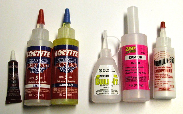 You’ll need some basic tools and construction materials, such as CA, epoxy glues and threadlocker. Photo 11 shows the products I used.
I’m quite pleased with the handsome, streamlined design of this little Yak 54. Thunder Tiger has carried through its semi-scale interpretation and delivered a model that is clearly Yak-like in both the appearance and flight envelope.
Thunder Tiger’s concern for quality showed in the extensive use of model-grade plywood bulkheads and hardened points. According to the Tower Hobbies website, the retail price of this ARF in the U.S. is $169.99.
Pre-Assembly Thoughts and Observations
Before setting off on my own to try to assemble this ARF, I took the box to Richard and Dan Landis’ workshop for a pre-assembly huddle. Some of the bullet points that I jotted down were:
• This is a lightweight airframe—keep it that way; no unneeded weight
• Use care—this fuselage was more fragile than my previous airplanes
• It is a tail-dragger with two-piece carbon struts for the main gear
• The molded plastic canopy needs to be carefully attached to its frame
• Use four high-torque metal gear microservos
• The ESC has a sufficient BEC (battery elimination circuit) output for four digital servos and receiver
• Use 3S1P packs with at least 3200mAh and 30C/60C capacity
• Try the recommended 13 x 4E propeller first; later the 12 x 6E
You’ll need some basic tools and construction materials, such as CA, epoxy glues and threadlocker. Photo 11 shows the products I used.
I’m quite pleased with the handsome, streamlined design of this little Yak 54. Thunder Tiger has carried through its semi-scale interpretation and delivered a model that is clearly Yak-like in both the appearance and flight envelope.
Thunder Tiger’s concern for quality showed in the extensive use of model-grade plywood bulkheads and hardened points. According to the Tower Hobbies website, the retail price of this ARF in the U.S. is $169.99.
Pre-Assembly Thoughts and Observations
Before setting off on my own to try to assemble this ARF, I took the box to Richard and Dan Landis’ workshop for a pre-assembly huddle. Some of the bullet points that I jotted down were:
• This is a lightweight airframe—keep it that way; no unneeded weight
• Use care—this fuselage was more fragile than my previous airplanes
• It is a tail-dragger with two-piece carbon struts for the main gear
• The molded plastic canopy needs to be carefully attached to its frame
• Use four high-torque metal gear microservos
• The ESC has a sufficient BEC (battery elimination circuit) output for four digital servos and receiver
• Use 3S1P packs with at least 3200mAh and 30C/60C capacity
• Try the recommended 13 x 4E propeller first; later the 12 x 6E

 For the radio components I am using my six-channel Futaba 6EX 2.4 GHz spread spectrum transmitter and a matching R617FS seven-channel receiver (Photos above). You might prefer to put each aileron servo on its own channel, but I chose to follow the manual for this review and used a Y-connector instead.
 The ESC supplied by Great Planes, the ElectriFly SS45A, is shown in Photo 12. It has a BEC built in. Since the receiver and four digital HT servos will get power directly from the flight battery (eliminating the need for a separate receiver battery pack), I needed to double-check the BEC specs.
 The Yak 54 manual recommends a 3S1P 11.1V 2200mAh LiPo flight battery. From his experience with 3-D airplanes of this size, Dan Landis suggested I consider a 3300mAh 3S1P Sky LiPo Ultimate Charge Series (from www.hobbypartz.com) with 30C continuous and 60C burst capacity (Photo above).
Why Sky LiPo? I had been watching Dan prepare for the summer’s Nats using this brand of LiPo pack—what works for his exacting Pattern airplanes is surely good enough for my application.
These packs have two metal alloy heat-sink plates built in and the charge/balance taps fit into the GP/KO adapter of my FMA Direct Cellpro Multi4 charger. The only glitch is that this pack comes with a 4.0 banana-plug output connector. In order to be compatible with other equipment I use, I needed to carefully remove it and solder in its place a W.S. Deans 2-Pin Female Ultra Plug connector. At some point in the future I may consider changing over to banana plugs on all my equipment.
The Yak 54 manual recommends a 3S1P 11.1V 2200mAh LiPo flight battery. From his experience with 3-D airplanes of this size, Dan Landis suggested I consider a 3300mAh 3S1P Sky LiPo Ultimate Charge Series (from www.hobbypartz.com) with 30C continuous and 60C burst capacity (Photo above).
Why Sky LiPo? I had been watching Dan prepare for the summer’s Nats using this brand of LiPo pack—what works for his exacting Pattern airplanes is surely good enough for my application.
These packs have two metal alloy heat-sink plates built in and the charge/balance taps fit into the GP/KO adapter of my FMA Direct Cellpro Multi4 charger. The only glitch is that this pack comes with a 4.0 banana-plug output connector. In order to be compatible with other equipment I use, I needed to carefully remove it and solder in its place a W.S. Deans 2-Pin Female Ultra Plug connector. At some point in the future I may consider changing over to banana plugs on all my equipment.
 This pack worked out well in this model’s power system. The amount of power output is remarkable; it fits comfortably on the battery tray (Photo above), and the pack’s weight (280 grams) allows for easy CG balancing. After trying one pack I purchased three more.
Safety arming switch: I had installed an arming switch between the flight battery and the ESC in each of the two previous aircraft. I do believe in them for safety, although I deliberately did not put one in the Yak 54.
If I reconsider in the future I would choose to use a product such as the MPI Maxx Products International #6970 High Current Arming Switch, which cuts off power to the entire system when the arming plug is pulled out. On a 3-D-capable airplane such as this one, be sure your arming plug cannot be loosened under the G-loads, since receiver power would be lost if it fell out!
This pack worked out well in this model’s power system. The amount of power output is remarkable; it fits comfortably on the battery tray (Photo above), and the pack’s weight (280 grams) allows for easy CG balancing. After trying one pack I purchased three more.
Safety arming switch: I had installed an arming switch between the flight battery and the ESC in each of the two previous aircraft. I do believe in them for safety, although I deliberately did not put one in the Yak 54.
If I reconsider in the future I would choose to use a product such as the MPI Maxx Products International #6970 High Current Arming Switch, which cuts off power to the entire system when the arming plug is pulled out. On a 3-D-capable airplane such as this one, be sure your arming plug cannot be loosened under the G-loads, since receiver power would be lost if it fell out!
 Servos: An electric-power system eliminates the need for a throttle servo because the “throttle” function is handled by the ESC. I purchased four Futaba S3156 microservos to install on the two ailerons, rudder and elevator (Photo above). Notice the red heat shrink that permanently “locks” the connectors together.
Also, two 12-inch servo extension cables will connect the tail-mounted elevator and rudder servos to the receiver. A Y-connector connects the two aileron servos to Channel 1 of the receiver; it allows enough slack for easy wing removal and attachment, but I found the Yak 54 fits in the trunk of my car without bothering to take off the wing halves.
Assembly Notes
I always read the assembly manual before beginning a new assembly and make some notes in pencil in the margins during the assembly. My impression is that, unlike the two trainers I’ve assembled, Thunder Tiger assumes prior ARF assembly experience with this model.
The Yak 54 manual indicates what to do, but often does not go into detail on how. For example, I had a number of questions about how best to mount the plastic canopy to its balsa frame (manual Step 34), and similarly, how best to position and mount the cowl, how to balance the propeller, and how to perform the longitude balance (page 13). But I have learned enough to know when to ask a more experienced modeler for assistance.
The manual also assumes you know how to use blue threadlocker on set screws and motor mount screws, how to place a drop of thin CA in balsa pilot holes, how to decide exactly where control-horn pilot holes are placed; etc. Do not expect a tutorial.
Here are my assembly notes, roughly in the order of the manual’s assembly steps. If you are considering assembling this model, you may want to download a copy of the assembly manual (www.ttamerica.com/airplanes/ttra4349.html or www.manuals.hobbico.com/ttr/ttra4349-manual.pdf) and follow along.
The printed assembly manual is heavily illustrated with as many as six black-and-white photographs on a page, but for those that lack contrast I refer to the PDF version of the downloaded manual and enlarge any critical photos on my computer screen.
Thunder Tiger’s suggested order of assembly is roughly the wing assembly, tail feather assembly (including the tail wheel), electric-motor installation, landing-gear installation, receiver and battery installation, fuselage assembly (including the canopy), cowl installation, control throws, balancing, and pre-flight instructions.
I will touch on these briefly and comment where necessary.
Parts: First, I checked the included parts and pencil-checked the parts drawings on pages 4 and 5 as I located each one. The parts drawings are not to scale; use a metric ruler for the millimeter sizes. This step took some time because the parts are in several sealed plastic bags, shown in Photo 8.
Servos: An electric-power system eliminates the need for a throttle servo because the “throttle” function is handled by the ESC. I purchased four Futaba S3156 microservos to install on the two ailerons, rudder and elevator (Photo above). Notice the red heat shrink that permanently “locks” the connectors together.
Also, two 12-inch servo extension cables will connect the tail-mounted elevator and rudder servos to the receiver. A Y-connector connects the two aileron servos to Channel 1 of the receiver; it allows enough slack for easy wing removal and attachment, but I found the Yak 54 fits in the trunk of my car without bothering to take off the wing halves.
Assembly Notes
I always read the assembly manual before beginning a new assembly and make some notes in pencil in the margins during the assembly. My impression is that, unlike the two trainers I’ve assembled, Thunder Tiger assumes prior ARF assembly experience with this model.
The Yak 54 manual indicates what to do, but often does not go into detail on how. For example, I had a number of questions about how best to mount the plastic canopy to its balsa frame (manual Step 34), and similarly, how best to position and mount the cowl, how to balance the propeller, and how to perform the longitude balance (page 13). But I have learned enough to know when to ask a more experienced modeler for assistance.
The manual also assumes you know how to use blue threadlocker on set screws and motor mount screws, how to place a drop of thin CA in balsa pilot holes, how to decide exactly where control-horn pilot holes are placed; etc. Do not expect a tutorial.
Here are my assembly notes, roughly in the order of the manual’s assembly steps. If you are considering assembling this model, you may want to download a copy of the assembly manual (www.ttamerica.com/airplanes/ttra4349.html or www.manuals.hobbico.com/ttr/ttra4349-manual.pdf) and follow along.
The printed assembly manual is heavily illustrated with as many as six black-and-white photographs on a page, but for those that lack contrast I refer to the PDF version of the downloaded manual and enlarge any critical photos on my computer screen.
Thunder Tiger’s suggested order of assembly is roughly the wing assembly, tail feather assembly (including the tail wheel), electric-motor installation, landing-gear installation, receiver and battery installation, fuselage assembly (including the canopy), cowl installation, control throws, balancing, and pre-flight instructions.
I will touch on these briefly and comment where necessary.
Parts: First, I checked the included parts and pencil-checked the parts drawings on pages 4 and 5 as I located each one. The parts drawings are not to scale; use a metric ruler for the millimeter sizes. This step took some time because the parts are in several sealed plastic bags, shown in Photo 8.

 Wing Assembly: The wing’s four-color covering scheme looks sharp, and the underside of each wing is covered in a contrasting silver with black stripes, to differentiate upright from inverted flight (Photos above).
The wing halves are pre-slotted for four CA hinges each, which are included. Apply CA to the hinges on the aileron, position the aileron against the wing and apply CA to both sides of the hinges into the wing’s trailing edge.
Wing Assembly: The wing’s four-color covering scheme looks sharp, and the underside of each wing is covered in a contrasting silver with black stripes, to differentiate upright from inverted flight (Photos above).
The wing halves are pre-slotted for four CA hinges each, which are included. Apply CA to the hinges on the aileron, position the aileron against the wing and apply CA to both sides of the hinges into the wing’s trailing edge.
 Photo above shows the Yak 54’s symmetrical airfoil and wing construction.

 The Yak 54 is designed for straightforward attachment and removal of the wing halves using a carbon-fiber wing joiner tube and two nylon retaining screws inside the fuselage. Slip the joiner tube into a wing half, push the tube into the socket (First photo above) until the wing half mates with the fuselage, and slip the other wing half onto the tube (see Photo above).
I used a covering iron to tack down the openings that are cut in for each wing’s aileron servo well. The Futaba S3156 servos fit the well with just a little play. I hand-drilled a 1/16-inch pilot hole and attached each servo with two screws. While the iron was hot I did the same for the elevator and rudder servo wells and servos.
The Yak 54 is designed for straightforward attachment and removal of the wing halves using a carbon-fiber wing joiner tube and two nylon retaining screws inside the fuselage. Slip the joiner tube into a wing half, push the tube into the socket (First photo above) until the wing half mates with the fuselage, and slip the other wing half onto the tube (see Photo above).
I used a covering iron to tack down the openings that are cut in for each wing’s aileron servo well. The Futaba S3156 servos fit the well with just a little play. I hand-drilled a 1/16-inch pilot hole and attached each servo with two screws. While the iron was hot I did the same for the elevator and rudder servo wells and servos.

 Control Horns: Thunder Tiger supplies four nylon control-surface horns. They are the type that has a single leg as opposed to those that use two screws and a nutplate for attachment. The first photo above shows both types side-by-side. Although I used the supplied horns in the two ailerons (because of their thickness), I chose to substitute Du-Bro 1/2A control horns for the elevator and the rudder (Photo above).
 A red arrow decal on the underside of each aileron points to the harden point where you need to carefully position and drill a 5/32-inch hole for the horn (Photo above). I chose to mount the servo arm, EZ connector, and pushrod first, because the servo well positions the servo on an angle (see the photo for Step 7 in the manual). By placing a straightedge along the pushrod’s path, I was able to mark the mounting-hole position in the aileron correctly. Roughen up the leg and use epoxy.

 Four EZ connectors (First photo above) are supplied, one for each servo. I chose to use substitute servo arms for the Futaba servos (Photo above).
 Attach the EZ connector to the top of each servo arm. You may have to enlarge the hole in the arm slightly—I used the outermost hole on each arm. Be sure to use blue threadlocker on the screw (see Photo above).
 Snap the Z-bend of the pre-formed pushrod into the control horn and then slide the straight end into the EZ connector and lightly tighten the set screw for now. Photo above shows the set-up for the port wing half. Note that the unused servo arm was removed, clipped off and filed, and the active arm points toward the wing tip.
Fuselage Assembly: Locate and cut the covering over the two openings in the underside of the fuselage; a double opening just aft of the landing gear, and a triangular opening near the tail. Use an iron to tack down the covering. Again, while the iron is hot, locate, cut, and tack down the slot on each side of the aft fuselage for the horizontal stabilizer.
Snap the Z-bend of the pre-formed pushrod into the control horn and then slide the straight end into the EZ connector and lightly tighten the set screw for now. Photo above shows the set-up for the port wing half. Note that the unused servo arm was removed, clipped off and filed, and the active arm points toward the wing tip.
Fuselage Assembly: Locate and cut the covering over the two openings in the underside of the fuselage; a double opening just aft of the landing gear, and a triangular opening near the tail. Use an iron to tack down the covering. Again, while the iron is hot, locate, cut, and tack down the slot on each side of the aft fuselage for the horizontal stabilizer.
 Canopy Assembly: This section of the fuselage assembly was probably the most difficult. The canopy is a thin, pre-painted plastic casting (Photo above).

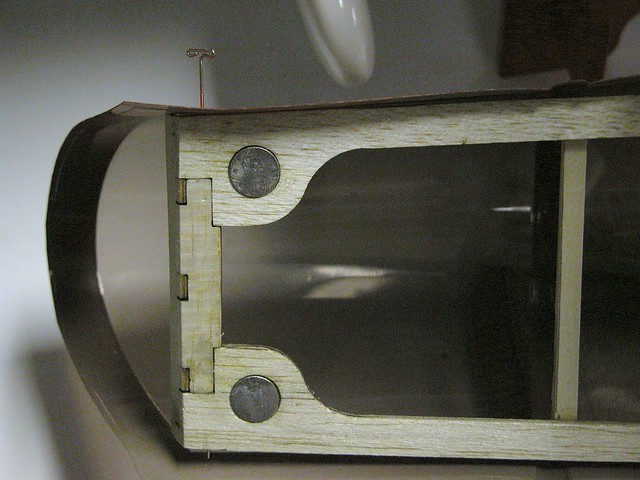 The canopy needs to be attached to a balsa frame (First photo above). Together, the canopy and frame form an ample hatch cover. I added the two cross braces with the dot on them to reinforce the frame where I would be grabbing the canopy to open the hatch cover. Even though the finished hatch cover has two small super magnets for closure (Photo above) and tucks under the rear edge of the cowl, I found that the canopy can self-eject under the rigors of 3-D flight, so I used a small piece of clear 3M tape to hold it down.
 I spent about an hour trying to get this done as well and as neat as possible; the painted finish is unforgiving to heat or acetone. There is no pilot figure supplied. You may not have noticed in the photo that I left the heads of two T-pins glued with CA in both aft corners to grip when pulling up on the back of the hatch.
 How does it look installed—not bad?

 Installing the Empennage: The empennage, or “tail feathers,” are the horizontal stabilizer and its left and right elevator (First photo above), and the vertical fin and its rudder (Photo above). This is a critical step because the ability of the Yak 54 to track true depends a great deal on the alignment of the horizontal and vertical surfaces. There will also be a lot of stress on both when in 3-D maneuvers, so use epoxy as much as possible.

 Do cut away the covering as instructed, but try not to “score” the balsa underneath (Photos 34 and 35). Be sure to attach the wing halves, dry-fit the stab and fin, and triple-check alignment before committing to glue. Use a modelers’ triangle or square and tape the surfaces in place until dry—overnight is preferred.
 Photo above shows waxed paper taped around the horizontal stabilizer to protect against the spread of the epoxy used to attach the elevator torque rod to the elevators.

 The assembled fin and rudder with tail wheel are shown in Photos above.
In both cases, make the gaps as uniform and as small as possible without binding. The goal is to avoid “flutter” of the huge, moveable control surfaces.
I attached the Du-Bro 1/2A control horns to the starboard side of the rudder and to the port elevator, as shown in the manual. Take your time and use care to align the screw holes for both sides of the elevator and rudder as accurately as possible.
There will be extra thread showing above each nutplate when you are done. You may want to use a T-pin forced through the balsa to mark the placement of the exit holes, then remove the T-pin and hand drill 5/64-inch holes.
Attach the rudder and elevator servos, running each servo extension cable through the fuselage into the open hatch area and tying them in place temporarily. Put on the servo arms and attach the EZ connectors and pushrods as done for the ailerons.
The assembled fin and rudder with tail wheel are shown in Photos above.
In both cases, make the gaps as uniform and as small as possible without binding. The goal is to avoid “flutter” of the huge, moveable control surfaces.
I attached the Du-Bro 1/2A control horns to the starboard side of the rudder and to the port elevator, as shown in the manual. Take your time and use care to align the screw holes for both sides of the elevator and rudder as accurately as possible.
There will be extra thread showing above each nutplate when you are done. You may want to use a T-pin forced through the balsa to mark the placement of the exit holes, then remove the T-pin and hand drill 5/64-inch holes.
Attach the rudder and elevator servos, running each servo extension cable through the fuselage into the open hatch area and tying them in place temporarily. Put on the servo arms and attach the EZ connectors and pushrods as done for the ailerons.

 Photos above show views of the elevator and rudder servos, and the pushrods and control horns.

 Main landing gear installation: Next, I assembled the carbon landing gear to the fuselage. The covering on the fuselage bottom has already been trimmed and tacked in the factory, revealing four mounting holes (Photos above).
 Look inside the fuselage, beneath the battery tray, and you will see the reinforced hardpoint that the gear fasteners pass through (Photo above). There is just enough room for a 7/32-inch nut driver to restrain the lock nuts during tightening. Use blue threadlocker here.
Be sure to place the two struts on the correct sides of the fuselage. The strut with the raised Thunder Tiger logo imprinted into it is the port side (pilot’s left). The Yak 54 gear angles forward a bit and looks slightly “bow legged.”
Look inside the fuselage, beneath the battery tray, and you will see the reinforced hardpoint that the gear fasteners pass through (Photo above). There is just enough room for a 7/32-inch nut driver to restrain the lock nuts during tightening. Use blue threadlocker here.
Be sure to place the two struts on the correct sides of the fuselage. The strut with the raised Thunder Tiger logo imprinted into it is the port side (pilot’s left). The Yak 54 gear angles forward a bit and looks slightly “bow legged.”

 My manual came with an addendum to Step 27, “Assembly of the Wheel Pants.” First photo above shows the groove and the reinforcing plate inside of each wheel pant. Assembled as diagrammed; I slipped a 7/16-inch open-end wrench inside the pant to hold the axle still while tightening the locknut with a 9/32-inch driver. I ground a flat on the axle where the set screw of the collar hits it.
Be sure to set the Yak 54 on a flat surface and adjust the angle of both wheel pants before locking their position with the 2.3 x 8 mm wood screws. Photo above shows a bottom view of the Yak 54 with landing gear and all control surfaces attached.
My manual came with an addendum to Step 27, “Assembly of the Wheel Pants.” First photo above shows the groove and the reinforcing plate inside of each wheel pant. Assembled as diagrammed; I slipped a 7/16-inch open-end wrench inside the pant to hold the axle still while tightening the locknut with a 9/32-inch driver. I ground a flat on the axle where the set screw of the collar hits it.
Be sure to set the Yak 54 on a flat surface and adjust the angle of both wheel pants before locking their position with the 2.3 x 8 mm wood screws. Photo above shows a bottom view of the Yak 54 with landing gear and all control surfaces attached.
 Power Unit Installation: If you are using the Thunder Tiger Ripper outrunner motor that comes with this version of the Yak 54, follow the instructions for an uncomplicated installation (see next five photos).

 First photo above shows the firewall and pre-installed motor-mount box. Photo above shows the assembled Ripper OBL36/09-30A motor and leads. Use blue threadlocker on all screws.
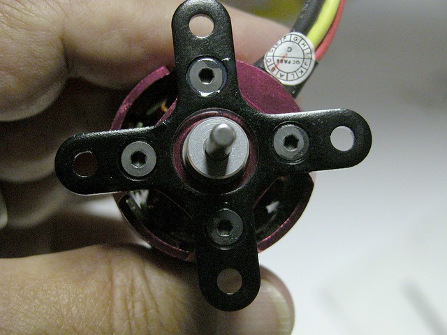
 An X-mounting plate is attached to the motor (First photo above) and then to the face of the pre-assembled motor box (Photo above), which I blackened with permanent marker for appearance.
 The SS45A ESC shown earlier was tie-wrapped onto the port side of the fuselage close to the generous air opening in the cowl for good cooling (Photo above). I ran the three lead wires forward through the firewall to the motor.
I was surprised that the female bullet connectors on the three leads of the ESC were not a tight fit with the mating male connectors on the OBL motor. I removed them and replaced them with 4 mm Du-Bro female connectors and new heat-shrink tubing and tie-wrapped the leads in place.
I installed my flight battery of choice, a Sky LiPo 3S1P 11.1V 3300mAh 30C/60C pack, using a strip of hook and eye fastener material glued with CA to the battery tray and a corresponding short length on the back of each 3S1P pack.
In addition, I used not one, but two battery straps around the head and around the foot of the pack, to hold it tightly to the tray; you do not want to risk the battery (and therefore the CG) shifting during 3-D maneuvers!
The SS45A ESC shown earlier was tie-wrapped onto the port side of the fuselage close to the generous air opening in the cowl for good cooling (Photo above). I ran the three lead wires forward through the firewall to the motor.
I was surprised that the female bullet connectors on the three leads of the ESC were not a tight fit with the mating male connectors on the OBL motor. I removed them and replaced them with 4 mm Du-Bro female connectors and new heat-shrink tubing and tie-wrapped the leads in place.
I installed my flight battery of choice, a Sky LiPo 3S1P 11.1V 3300mAh 30C/60C pack, using a strip of hook and eye fastener material glued with CA to the battery tray and a corresponding short length on the back of each 3S1P pack.
In addition, I used not one, but two battery straps around the head and around the foot of the pack, to hold it tightly to the tray; you do not want to risk the battery (and therefore the CG) shifting during 3-D maneuvers!

 Cowl Installation: The pre-painted fiberglass cowl is beautifully formed and has a large opening for air intake, even without the scale cowl vents that are seen on larger Yak 54 models. (Photos above.)
 Position the canopy/hatch in place, then test fit the cowl by tacking it in place with small strips of clear tape as you carefully align its decorative stripes with those on each side of the fuselage (Photo above).

 Allow enough room for the propeller adapter to extend past the cowl to avoid the propeller rubbing against the front of the cowl (First photo above). Center the motor and propeller adapter in the opening, as in second photo above.
Secure the cowl with four 2.3 x 8 mm wood screws; two on each side. Position the screws into the sheeted areas of the fuselage and place a drop of CA in each pilot hole to toughen the wood.
Allow enough room for the propeller adapter to extend past the cowl to avoid the propeller rubbing against the front of the cowl (First photo above). Center the motor and propeller adapter in the opening, as in second photo above.
Secure the cowl with four 2.3 x 8 mm wood screws; two on each side. Position the screws into the sheeted areas of the fuselage and place a drop of CA in each pilot hole to toughen the wood.

 Mount the propeller and this step is finished (First photo above). I suggest that you balance the propeller before flying, using any of the available devices and techniques. I used the Du-Bro balancer, pictured in photo above.
An attractive, semi-scale look: The only concern—and this is nit-picking—is that the red colorings of the plastic canopy, the Oracover scheme’s red swash, and the red painted cowl are close but not quite a dead-on color match.
Mount the propeller and this step is finished (First photo above). I suggest that you balance the propeller before flying, using any of the available devices and techniques. I used the Du-Bro balancer, pictured in photo above.
An attractive, semi-scale look: The only concern—and this is nit-picking—is that the red colorings of the plastic canopy, the Oracover scheme’s red swash, and the red painted cowl are close but not quite a dead-on color match.
 Radio Installation: As mentioned above, I chose to use an existing Futaba 6EX 2.4 GHz FASST transmitter and matching Futaba 2.4 GHz FASST R617FS receiver. Four Futaba S3156 MG HT micro digital servos and three channels were used to control the ailerons (two servos via a Y-connector), elevator, and rudder. Throttle was Channel 3 to the ESC. It all fit neatly in the Yak 54’s spacious electronics bay (see photo above).
 I added a pressure-sensitive cable guide attached to the foam shell of the aft deck to keep the 12-inch servo extensions of the tail-mounted elevator and rudder servos from chafing (Photo above).
Make sure the control surfaces are taped in neutral position and that each servo is centered before you adjust the pushrod assemblies, using the set screw on each EZ connector. It is better to adjust and check multiple times until you have a reasonable geometry than to use the trim settings in your transmitter.
Note: Particularly for electrical power systems, never test and adjust the control surface servos, linkages or throttle with a propeller mounted on the motor. Always treat the motor as if it did have a propeller on it that could start to spin at any moment without warning. You do not want to see how easily an unexpected spinning propeller can absolutely ruin your day.
The Futaba R617FS receiver does not recommend wrapping it in foam rubber; instead, I used a piece of Hobbico ¼-inch foam rubber between the receiver and the plywood tray. The antenna on this type of receiver is a short pair of insulated antenna leads, which were taped against the fuselage at right angles to each other for best reception.
If you are using FM or other technology, run your antenna out through the opening in the bottom rear of the fuselage, as described in the manual.
I added a pressure-sensitive cable guide attached to the foam shell of the aft deck to keep the 12-inch servo extensions of the tail-mounted elevator and rudder servos from chafing (Photo above).
Make sure the control surfaces are taped in neutral position and that each servo is centered before you adjust the pushrod assemblies, using the set screw on each EZ connector. It is better to adjust and check multiple times until you have a reasonable geometry than to use the trim settings in your transmitter.
Note: Particularly for electrical power systems, never test and adjust the control surface servos, linkages or throttle with a propeller mounted on the motor. Always treat the motor as if it did have a propeller on it that could start to spin at any moment without warning. You do not want to see how easily an unexpected spinning propeller can absolutely ruin your day.
The Futaba R617FS receiver does not recommend wrapping it in foam rubber; instead, I used a piece of Hobbico ¼-inch foam rubber between the receiver and the plywood tray. The antenna on this type of receiver is a short pair of insulated antenna leads, which were taped against the fuselage at right angles to each other for best reception.
If you are using FM or other technology, run your antenna out through the opening in the bottom rear of the fuselage, as described in the manual.
 Assembly Completed
The Thunder Tiger Yak 54 3D Brushless ARF is now fully assembled. It is a really nice-looking aircraft; definitively sculpted and streamlined, with a high-value finished appearance. Looking at it on the shop floor I feel this kit is an excellent value (Photo above). I can’t wait to see how it performs in the air!
But before you run out to the field to fly, take this time to carefully go over all instructions, every fit, and every screw. Then you should carefully adjust the control throws and balance before you go.
Control Throws: The manual’s illustrations (page 12) explain how much each control surface should move in response to the control sticks on your transmitter in low-rate and high-rate switch positions. It is wise to start with the manufacturer’s recommendations for the first few flights. That said, an experienced flier ought to review these settings before taking the Yak 54—or any new model—up in the air. It could mean the difference between a successful maiden experience and a disastrous one.
Assembly Completed
The Thunder Tiger Yak 54 3D Brushless ARF is now fully assembled. It is a really nice-looking aircraft; definitively sculpted and streamlined, with a high-value finished appearance. Looking at it on the shop floor I feel this kit is an excellent value (Photo above). I can’t wait to see how it performs in the air!
But before you run out to the field to fly, take this time to carefully go over all instructions, every fit, and every screw. Then you should carefully adjust the control throws and balance before you go.
Control Throws: The manual’s illustrations (page 12) explain how much each control surface should move in response to the control sticks on your transmitter in low-rate and high-rate switch positions. It is wise to start with the manufacturer’s recommendations for the first few flights. That said, an experienced flier ought to review these settings before taking the Yak 54—or any new model—up in the air. It could mean the difference between a successful maiden experience and a disastrous one.
 I used a Hobbico AccuThrow deflection meter (Photo above) to carefully set up the low- and high-rate throws, as closely as possible. One issue I had was that the rudder control horn did not allow a full 3-inch deflection because it contacts the vertical fin, even with some of the horn cut away. Dan’s test flights showed these deflections sufficient to accomplish every maneuver in the repertoire. See the “Throws” chart at the end of this review.
Expo: I added 30% (-30) of expo in the Futaba transmitter program for the Yak 54’s ailerons, 40% expo for the elevators, and 30% for the rudder. I have not yet used either of the two available programmable mixes.
Balancing: For a Sport model aircraft, balance is very important; for a 3-D-capable model, balancing is critical. Although this ARF is pre-fabricated and came with the recommended brushless outrunner motor and all of the hardware, there is still room for variation in the weights and form factors of the receiver, speed control, servos, battery pack, and propeller.
Because of this flexibility, there is a reasonable chance that the assembled Yak 54 will not balance exactly at the manufacturer’s recommended CG of 3 ¼-inches aft of the wing’s leading edge.
Install all equipment and the flight battery, but do not connect it to the ESC. Using a balancer or your fingers, carefully hold the airplane at the CG point in the manual and see that it is level.
In my case, the Yak 54 was a bit nose heavy, even though I shifted the flight battery’s position on the battery tray. I added self-adhesive ¼-ounce lead weights in the fuselage’s tail, through the convenient triangular tail opening at the bottom of the fuselage until the Yak 54 balanced at the recommended CG. In this case I added ¾ ounces of weight from a package that held 6 ounces.
The assembly manual discusses longitude balance on page 13, but I have to admit the recommended procedure escaped me. I did check lateral balance by holding the airframe by the motor shaft and by a thin wire through the rudder hinge-gap.
I used a Hobbico AccuThrow deflection meter (Photo above) to carefully set up the low- and high-rate throws, as closely as possible. One issue I had was that the rudder control horn did not allow a full 3-inch deflection because it contacts the vertical fin, even with some of the horn cut away. Dan’s test flights showed these deflections sufficient to accomplish every maneuver in the repertoire. See the “Throws” chart at the end of this review.
Expo: I added 30% (-30) of expo in the Futaba transmitter program for the Yak 54’s ailerons, 40% expo for the elevators, and 30% for the rudder. I have not yet used either of the two available programmable mixes.
Balancing: For a Sport model aircraft, balance is very important; for a 3-D-capable model, balancing is critical. Although this ARF is pre-fabricated and came with the recommended brushless outrunner motor and all of the hardware, there is still room for variation in the weights and form factors of the receiver, speed control, servos, battery pack, and propeller.
Because of this flexibility, there is a reasonable chance that the assembled Yak 54 will not balance exactly at the manufacturer’s recommended CG of 3 ¼-inches aft of the wing’s leading edge.
Install all equipment and the flight battery, but do not connect it to the ESC. Using a balancer or your fingers, carefully hold the airplane at the CG point in the manual and see that it is level.
In my case, the Yak 54 was a bit nose heavy, even though I shifted the flight battery’s position on the battery tray. I added self-adhesive ¼-ounce lead weights in the fuselage’s tail, through the convenient triangular tail opening at the bottom of the fuselage until the Yak 54 balanced at the recommended CG. In this case I added ¾ ounces of weight from a package that held 6 ounces.
The assembly manual discusses longitude balance on page 13, but I have to admit the recommended procedure escaped me. I did check lateral balance by holding the airframe by the motor shaft and by a thin wire through the rudder hinge-gap.

 The Yak 54’s 45-inch wingspan allows it to fit snuggly in the trunk of my Nissan Altima 2.4SL—without having to remove the wing halves. Perfect for us lazy types (First photo above), it can go right from my trunk to the set-up table, and back again at the end of the day (Photo above).
Ready to Test-Fly
A wise beginner—and even most intermediate pilots—will not attempt to maiden his or her newly assembled airplane. Leave this to the best pilot you can find; one who is willing to help you. Most clubs have several people who regularly do this for others. In my club, that role is often played by Dan Landis. Dan is a great guy, a highly ranked national RC competitor, and also a professional full-scale pilot.
The Yak 54’s 45-inch wingspan allows it to fit snuggly in the trunk of my Nissan Altima 2.4SL—without having to remove the wing halves. Perfect for us lazy types (First photo above), it can go right from my trunk to the set-up table, and back again at the end of the day (Photo above).
Ready to Test-Fly
A wise beginner—and even most intermediate pilots—will not attempt to maiden his or her newly assembled airplane. Leave this to the best pilot you can find; one who is willing to help you. Most clubs have several people who regularly do this for others. In my club, that role is often played by Dan Landis. Dan is a great guy, a highly ranked national RC competitor, and also a professional full-scale pilot.

 My Thunder Tiger Yak 54 3D Brushless ARF was maidened on a Friday afternoon in mid-June, 2011, at HVRCC’s Haverstraw Model Aerodrome.
HVRCC’s field is a picturesque site overlooking the Hudson River, with a neatly manicured grass flying field. It sits at 108 feet of elevation. The weather was changing, but basically 75° F, 89% humidity, with the wind out of the south/southeast at 5-8 mph and gusting to 17 mph.
Unfortunately a front moved into the area quickly and cut short our window of opportunity. When the thunder and lightening arrived, we had to pack up and leave.
My Thunder Tiger Yak 54 3D Brushless ARF was maidened on a Friday afternoon in mid-June, 2011, at HVRCC’s Haverstraw Model Aerodrome.
HVRCC’s field is a picturesque site overlooking the Hudson River, with a neatly manicured grass flying field. It sits at 108 feet of elevation. The weather was changing, but basically 75° F, 89% humidity, with the wind out of the south/southeast at 5-8 mph and gusting to 17 mph.
Unfortunately a front moved into the area quickly and cut short our window of opportunity. When the thunder and lightening arrived, we had to pack up and leave.

 Dan was able to perform one short flight with the Yak 54 that day. But what a flight! While I stood by nervously, Dan put the airplane through a variety of successful, clean maneuvers: blenders, waterfalls, rolling harriers, inverted and upright harriers, high-alpha knife-edge … it was beautiful to watch. See photos (below) which were taken by Richard Landis.

 Here are Dan’s comments:
“Surprisingly, no trim clicks or re-balancing were needed. That’s unusual for a maiden flight.
“The plane feels good, solid, but light on the sticks with no surprises. Even with a 13 x 4 prop it had plenty of power for 3-D maneuvers. There was plenty of control surface throw in both low and high rate, yet in low rate it was gentle.
“It is very stable in the high-alpha regime and delivered a clean vertical line. It could benefit by adding one or two of the program mixes available on the 6EX transmitter.”
Here are Dan’s comments:
“Surprisingly, no trim clicks or re-balancing were needed. That’s unusual for a maiden flight.
“The plane feels good, solid, but light on the sticks with no surprises. Even with a 13 x 4 prop it had plenty of power for 3-D maneuvers. There was plenty of control surface throw in both low and high rate, yet in low rate it was gentle.
“It is very stable in the high-alpha regime and delivered a clean vertical line. It could benefit by adding one or two of the program mixes available on the 6EX transmitter.”

 In first photo above, Dan is transitioning the Yak 54 from an upright harrier to an inverted harrier:
“The airplane is very stable and needs very little rudder to keep the nose straight during the pull.”
Dan put the Yak 54 into an upright harrier, preparing to start a rolling harrier in photo above.
In first photo above, Dan is transitioning the Yak 54 from an upright harrier to an inverted harrier:
“The airplane is very stable and needs very little rudder to keep the nose straight during the pull.”
Dan put the Yak 54 into an upright harrier, preparing to start a rolling harrier in photo above.

 The photos above show the Yak 54 in a left rolling harrier, directly over the camera and maintaining a hover. In the photo below, Dan has the Yak 54 maintaining the hover.
“Up elevator was needed to keep the nose straight due to a strong crosswind.”
The photos above show the Yak 54 in a left rolling harrier, directly over the camera and maintaining a hover. In the photo below, Dan has the Yak 54 maintaining the hover.
“Up elevator was needed to keep the nose straight due to a strong crosswind.”
 That aggressive 3-plus minute flight used only about a third of the Sky LiPo pack’s capacity; I put back 1,103 mA out of 3,300 mA. I was relieved to see that the 13 x 4 propeller delivered enough power for Dan’s maneuvers; it will be very interesting to see how the Yak 54 performs with the 12 x 6 propeller recommended by Thunder Tiger for 3-D.
The next day was Saturday, June 18. Richard Landis, president of RCRCC and the CD for this fly-in, as well as Dan Landis and myself, attended the second annual Warwick R/C Model Fly-In, at the Warwick Municipal Airport, Warwick, New York. Seventy-four AMA pilots, together with their crew and family members, gathered at this beautiful full-scale airport for a day of unlimited RC flying, food, fun, and camaraderie.
This event was sanctioned by the AMA and several AMA staff were present, including District II Vice President Gary Fitch and Associate Vice President Frank Granelli.
The weather cooperated, too, with 0-6 mph winds out of the south/southwest. After the morning fog burned off, we had sun and 82° F with a bit of humidity.
The pit area was filled with animated modelers and crews, and crammed with pop-up tents and aircraft of all sizes and types. You can view several videos of the Warwick event on YouTube.
That aggressive 3-plus minute flight used only about a third of the Sky LiPo pack’s capacity; I put back 1,103 mA out of 3,300 mA. I was relieved to see that the 13 x 4 propeller delivered enough power for Dan’s maneuvers; it will be very interesting to see how the Yak 54 performs with the 12 x 6 propeller recommended by Thunder Tiger for 3-D.
The next day was Saturday, June 18. Richard Landis, president of RCRCC and the CD for this fly-in, as well as Dan Landis and myself, attended the second annual Warwick R/C Model Fly-In, at the Warwick Municipal Airport, Warwick, New York. Seventy-four AMA pilots, together with their crew and family members, gathered at this beautiful full-scale airport for a day of unlimited RC flying, food, fun, and camaraderie.
This event was sanctioned by the AMA and several AMA staff were present, including District II Vice President Gary Fitch and Associate Vice President Frank Granelli.
The weather cooperated, too, with 0-6 mph winds out of the south/southwest. After the morning fog burned off, we had sun and 82° F with a bit of humidity.
The pit area was filled with animated modelers and crews, and crammed with pop-up tents and aircraft of all sizes and types. You can view several videos of the Warwick event on YouTube.

 I brought the Yak 54 along, hoping that Dan would have a chance to take it up again (Photos above); I was not ready to chance flying it with all the action in the pattern, and the number of spectators on the grounds. Safety is key.
Here is a two-minute video taken by RCRCC’s Ed Johnson, from his video coverage of this event. It shows snippets of Frank Granelli’s first flight with this airplane and my transmitter. Frank flies Masters level and is a highly skilled aeromodeler.
I brought the Yak 54 along, hoping that Dan would have a chance to take it up again (Photos above); I was not ready to chance flying it with all the action in the pattern, and the number of spectators on the grounds. Safety is key.
Here is a two-minute video taken by RCRCC’s Ed Johnson, from his video coverage of this event. It shows snippets of Frank Granelli’s first flight with this airplane and my transmitter. Frank flies Masters level and is a highly skilled aeromodeler.
Dan also took the Yak 54 up and started to put it through its paces, but the force he generated ejected the canopy—which can be seen flying away—before he deftly landed the now “open-cockpit” Yak (I added a larger piece of clear 3M tape to hold down the aft edge of the hatch).
Using a 13 x 4E APC propeller, there was 2 ½-inches of ground clearance in Warwick’s double-cut and rolled-grass runway. For home-field practice, I am considering taking off the wheel pants and exchanging the 2-inch wheels for 3 or 3 ½-inch wheels. If I do that I might have to re-balance the aircraft.
Personal Styles: I learned an interesting lesson about “balance” during the Yak 54’s early test flights, namely that two experienced pilots may have very different feels for “correct 3-D balance” of the same model airplane.
For example, during Dan’s initial flights he reported the Yak 54’s balance felt fine as built, not even adding any clicks of digital trim. On the other hand, Frank Granelli flew it after Dan and he felt the model was too tail heavy; the high rates could use more throw and the 13 x 4 propeller gave insufficient thrust.
Frank would prefer to have most of the tail weight removed and the recommended 12 x 6 propeller installed, which I will test and report back in Part Two, along with my own hands-on flight experience.
Watching Frank’s and Dan’s flights gave me a thrill that every modeler will recognize. It comes when you realize that the kit or ARF and miscellaneous components which you carefully selected, installed, adjusted, tweaked, and tested have turned into that graceful flying machine silhouetted against the clouds.
Summary
Clearly, the Thunder Tiger Yak 54 3D Brushless ARF is well conceived and of quality construction. It is a pleasing implementation of the “Yak 54 design,” and is priced right, in my opinion. Without counting time spent taking notes and photographs for this review, the assembly of this ARF would have taken me three, maybe four, evenings to assemble.
The Yak 54 handled well in all attitudes and transitions. Dan has since flown it again and remains pleased with its performance and stability. We can heartily recommend the Thunder Tiger Yak 54 3D Brushless ARF as a platform for aspiring aerobatic fliers.
Whether it is suitable as a “third airplane” choice for relatively new fliers will depend on how I manage to learn to handle it. That said, I am looking forward to getting some “stick time” with this capable airplane; my goal is to practice and report back to you in Part Two of this review.
Stay tuned.
Specifications (as built):
Wing Span: 45 inches
Length: 45 ½ inches
Wing Area: 382 square inches
Weight: 1.98 pounds/31.6 ounces
AUW: 2.593 pounds/41.48 ounces
Motor: TT Ripper OBL36/09-30A outrunner brushless, supplied
Propeller: APC 13 x 4E Thin Electric #LP13040ESubstitutions used in this review:ESC: Great Planes Silver Series 45A Brushless ESC, 5V/2A BEC
Radio: Futaba 6EX 2.4 GHz six-channel FASST
Receiver: Futaba R617FS seven-channel FASST
Servos: Four Futaba S3156 Micro-Digital HT MG
Flight Battery: SKY LiPo 3S1P 3300mAh 11.1V 30C/60C Burst (280g) #77P-SL3300-3S1P-30C-3333
Propeller: APC 13 x 4E Thin Electric #LP13040E, or 12 x 5E Thin Electric
Y-Connector: Futaba EMS 12-inch cable
Servo Extension: Two 12-inch Futaba-type cables
Control Horns: Two Du-Bro 1/2A #107Other Measurements/Readings:Wing Load: 15.64 ounces per square foot
Wing Cubic: 9.6 ounces per cubic footThrows:
Low High
Ailerons 1 inch 2 inches *
Elevator 1 inch 1 3/8 inch
Rudder 1 ½ inches 1 ¾ inches **Manufacturer recommended throw in high rate is 3 inches.
Notable Positives:
• Clean implementation of Yak 54 design
• Excellent aerobatic and 3-D performance
• Straightforward assembly
• Pre-built motor mount
• Striking four-color Ultracote covering scheme
• Large hatch for easy battery swapping
• Fits in automobile trunkNotable Negatives:• English version of assembly manual needs work
• Canopy hold-down magnets insufficient
• Style of supplied control horns
• Slight mismatch of red cowl, canopy, and coveringManufacturer Websites: (alphabetical)Advanced Precision Composition (APC)
(530) 661-0399
www.apcprop.comDaniel Landis (Pilot)
[email protected]
www.danlandisinc.comDu-Bro Products, Inc. (Control Horns/Propeller Balancer)
(800) 848-9411
http://hobby.dubro.com/FMA Direct (CellPro Charger)
(301) 798-2770
www.fmadirect.comFutaba (Radio Transmitter and Receiver)
(217) 398-8970, extension 2
www.futaba-rc.comGreat Planes Model Distributors (ElectriFly/AccuThrow Deflection Meter)
(217) 398-8970
www.electrifly.com/index.html
www.greatplanes.com
HobbyPartz.com (Sky LiPo)
(626) 968-9860
www.hobbypartz.com/Knife Edge Software (RealFlight)
www.knifeedge.comMaxx Products International, LLC.
[email protected]
www.maxxprod.comRC Electronics, Inc. (WattsUp Meter)
(408) 705-1980
www.rc-cars-planes.com
Shulman Aviation (Super Cessna)
(407) 409-8000
www.shulmanaviation.com/Thunder Tiger Corporation (OBL 40 Trainer, Yak 54 3D ARF/Ripper)
(217) 398-8970
www.ttamerica.comTower Hobbies (Digital Mini-Tach)
(800) 637-6050
www.towerhobbies.comW.S. Deans Co. (Connectors)
(714) 828-6494
www.wsdeans.comPhoto credits:Ed Johnson—Video
Thunder Tiger—Photo 7
Futaba—Photos 11A and 11B
Richard Landis—Photos 1, 71–77
Barry Yarkon—Photos 2–6, 8–11, 12–70, 78-83
Image

Related Articles
Thunder Tiger Trainer 40 OBL ARF
Image

Written by Richard Landis and Barry Yarkon Digital Exclusive Follow along as a real-life beginner modifies the Thunder Power OBL Trainer to Electric Power under the tutelage of an experienced electric
Ready for less-than-perfect runways
Image

Arrows RC Husky 1800mm PNP Written by Jon Barnes Review As seen in the May 2020 issue of Model Aviation. Bonus Video At a Glance Specifications Model type: Electric STOL Skill level: Beginner to
Hangar 9 Fun Scale P-47 Thunderbolt PNP
Image

THIS P-47 LIVES UP TO THE “FUN” IN ITS NAME Hangar 9 Fun Scale P-47 Thunderbolt PNP By Fitz Walker Photos by Lee Ray and the author As seen in the March 2022 issue of Model Aviation At a Glance


Comments
Add new comment