
Written by Paul Kohlmann
A father-and-son build project takes to the air
Construction
As seen in the October 2013 issue of Model Aviation.
Specifications
Type: RC Scale Skill level: Intermediate builder; intermediate pilot Wingspan: 45 inches Wing area: 263 square inches Length: 35-3/16 inches Weight: 24 to 32 ounces Power: Two Blue Wonder 1,500 Kv motors; two 20-amp ESCs; and one 3S 2,200 mAh battery turning two APC 8 x 6 propellers Radio: Four-channel (aileron, elevator, throttle with differential thrust) Construction: Balsa and light plywood Finish: Heat-shrink film with painted trim and vinyl graphicsConstruction
I love nearly everything about RC flying—the variety, the history, and of course, the flying itself. But for me, the best part by far is scratch-building. I can spend hours studying other designers’ drawings, noodling over a project in CAD, or hunched over the building board in the garage. My attraction is largely in the craftsmanship. I enjoy building things by hand and like many scratch builders, I’m sorry to see that this aspect of our hobby is less prevalent than it once was. We tend to take it personally that most people don’t fully appreciate the joy that mumbling over a pile of sticks and breathing balsa dust can bring. It’s downright therapeutic! I was contemplating this one evening, while working on the prototype for one of my little fighter kits, when I heard a small voice over my shoulder: “Dad, I’ve been thinking. Maybe for your next project we could design and build something together.” It was my son, Drew, who was 10 years old at the time. I had hoped that Drew would develop an interest in building at some point, but I had decided to let him come to me rather than lead him by the nose. I was thrilled with Drew’s idea. I remember building my first plastic model with my dad on the Formica kitchen table when I was Drew’s age. That turned out to be quite a springboard, because I am still using the gifts of craftsmanship that he began handing down to me 40 years ago. Jumping at the chance to arm another generation, I readily agreed. I’m a Scale modeler at heart, so I suggested something simple and modest: a Stinson L5, but Drew had other ideas. “Let’s do a B-25! You know, with retractable landing gear and flaps and a bomb bay that works!” Crikey! I should have seen that coming. You see, Drew is a lucky kid who has been crawling all over a full-scale Mitchell for as long as he can remember. Until recently, a friend of ours owned one that was stationed at our local airport. But that seemed like a big job. I hadn’t even flown a twin yet in my relatively short RC career, let alone designed one. Plus it seemed like a lot to bite off for a kid. I didn’t want this to turn into a bonding project that gathers a mantle of dust and shame after the initial excitement dims. In the end we compromised. We dropped the retracts, flaps, and bomb drop (at least for the first article) and we made a blood pact that we would finish building the Sunday Punch if it killed us. When I was young, I took every shop class that was offered, including lots of drafting. As a result, when I started working with CAD as an engineer years ago, it was easy to grasp spatial relationships between components and views in the drawings. However, I really struggled with how to teach CAD to a kid who had no foundation.Image
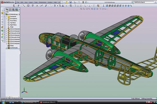
Image
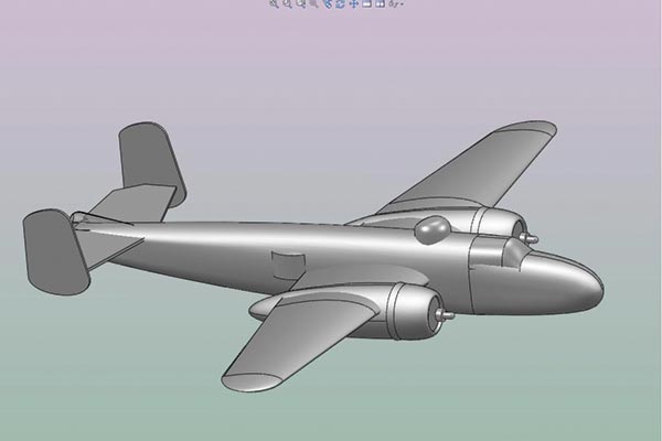
The B-25 Sunday Punch was designed in CAD.
Most kids today have an innate understanding of computers and video graphics that their parents do not. We do okay when we apply ourselves, but for most kids it is effortless. I was shocked (yes, jealous) at how Drew instantly understood how to lay out sketches on various airplanes and then span the gaps between them. He told me that it was similar to the Minecraft game that he plays online. Additionally, CAD has come a long way. Drew missed the DOS-based versions of CAD that I learned on. Today’s CAD is much more intuitive, driven by descriptive icons that represent common concepts such as Punch or Mirror. He picked these up quickly as well. Before we knew it we had a B-25 flying on our computer. Where Drew was disadvantaged was in the area of materials science. It takes a while to understand where to use plywood, what direction the balsa grain should run, and similar issues. I took on most of the conversion of the solid model into a framework and ultimately a laser-cut file. This kept the project alive and gave Drew time to solo his first RC airplane.
Construction
If you are interested in building this airplane, the plans and kit are available from Manzano Laser Works (see “Sources”). Construction on the Sunday Punch started with the tail group. Our basic premise was that this design should retain scale lines, but the emphasis was on quick building. The stock plans didn’t include functional rudders, but we provided a meaty center post for anyone interested in adding this feature. The horizontal stabilizer is sturdy enough for a light build but can be sheeted with 1/16-inch balsa for extra strength if retracts or larger motors are used. All of the outline parts for the tail are laser-cut and built over the plans. The bracing is 1/8 x 3/32 balsa strip stock. When cured, sand the tail group parts to shape. Separate the elevators and bevel their LEs to allow 3/8 inch of deflection. We used CA hinges and a music wire joiner rod to connect the elevators.Fuselage
For simplicity, our prototype used plug-in landing gear mounted to plywood formers in the nacelles and fuselage former F2. On a second build, the same formers were modified to accept retracts without servos. Alternatively, this Mitchell could be belly landed, but the belly and nacelles should be planked in the contact areas for durability. The top half of the fuselage is built over the plans. Start by pinning down the horizontal keel parts. Next, glue in all of the T formers. Ensure that they are all perpendicular to the board except F7—use the angle gauge on the plans to tip F7 backward. F7 forms the back of the battery hatch and the angle allows the hatch to easily lift off. Slide in the battery tray (BATT) and glue it into place along with the upper keel and wing pockets (WP) marked side facing out. Add some stringers to stiffen the structure. Alternating from left to right can minimize stress in the assembly, as can dampening the stringers before installation. After the upper fuselage is fully cured, unpin and flip it over. Glue in all B formers perpendicular to the horizontal keels. Assemble the servo tray and install the elevator servo, then mount it to F7b. The wing bolt pad (WB) is part of the servo tray, too. Epoxy a nylon 10-32 nut to the WB and then seal it in with all of those stringers. The battery is accessed from a hatch above the wing. Knock out the airfoil marked on the WPs. Slice through the upper keel and the stringers between the pairs of upper formers at F5 and F7 down to the airfoil opening. Carefully free the hatch.Wing
Because the Mitchell had distinctive gull wings, the wings are built as two inner and two outer panels. Each is assembled over the plans in the typical manner. The main spar consists of an upper and lower 1/8 x 3/32 balsa or basswood spar joined with full laser-cut shear webs. Pin down the TE, rear spar, and the lower main spar. Glue in the ribs, the upper main spar, and then the shear webs. Use the supplied angle gauge to tip ribs W1 and W6 to obtain the correct dihedral. All other ribs should be perpendicular to the board.Image
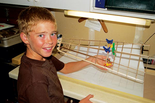
Drew had the task of joining the wing panels.
Fill in the aileron parts and the wingtips in the outer panels as shown. Join the inner and outer panels with plywood (BRACE2 and LE). Sheet the upper wing surface from the main spar to the LE with 1/32 balsa. Sheet the top and bottom between W1 and W2. Now glue a 3/8-inch soft balsa LE into place and sand it to the correct shape. Join the two wings with BRACE1. Slice through the TE where shown to free the ailerons. The aileron servos are attached to a plywood door that seats into a pocket between ribs W7 and W8. Add scrap wood to the corners of the pocket to hold the cover. Bevel the aileron’s LE for 3/8 inch of deflection and hang with hinges of your choice.
Nacelles
Glue vertical keel parts N1 and N2 perpendicular to middle former N3, and join N1 and N2 together where they form the rear of the nacelle. After it’s cured, glue in the firewall and the rear former halves N4 and N5. Now glue the lower wing pockets into place. Note that the orientation of N3 and the wing pocket parts is critical—make one left and one right nacelle. Add stringers to the lower nacelle from the firewall all the way back to the nacelle’s rear cone. Alternatively, stop the stringers at the rear former and use foam or balsa fill for the cone. Sheet the upper surface, leaving a rough opening for the wing. Now knock out the strip in the middle of N3 to allow the wing to pass through the nacelle. Slide the nacelle onto the wing, carefully trimming the upper half of the wing pockets until the nacelle slides home. The motor mounts are constructed from a balsa box with a plywood face. This assembly keys into the plywood firewall.Image
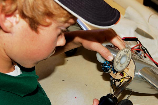
Drew shows off his soldering skills by connecting an ESC to a Blue Wonder motor.
Assembly
With all of the major subassemblies completed, fit the wing into the fuselage and install the wing pin in the wing’s LE. Fasten the TE with a nylon 10-32 screw threaded into the wing bolt pad. Adjust the fit of the battery hatch by sanding the wing pocket outline if needed. After the fit is correct, we used rare earth magnets to hold it down. Bevel F1 and F12 to fit the nose and tail cones. Epoxy the plywood cowl rings into the cowlings. The rings have two holes for 1/8-inch alignment pins. The other two holes are for magnets to hold the cowl against the firewall. We screwed our motor’s x-mounts to the plywood face of the motor box. The ESCs were stowed in the nacelles behind the firewalls. Battery wires and signal leads for the ESCs and ailerons were fished through the wings and exited through the upper center section into the battery hatch area where they met the receiver and the 3S 2,200 mAh LiPo.Image
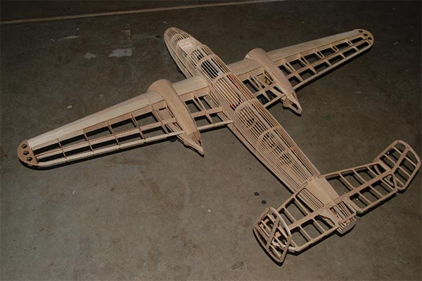
The B-25 Sunday Punch sets in the bones, ready for power and controls.
We covered our Sunday Punch with UltraCote ParkLite covering with excellent results. Cover all of the subassemblies, leaving holes under the wing to connect the motor wiring when the nacelles are installed. We used high-strength, clear silicone to fix the nacelles in place. The Mitchell’s low weight and the bond line around the two wing cutouts made silicone a good choice. A member of RCGroups made custom vinyl graphics for us that were perfect. Drew and I were anxious to get the model airborne, so we limited the detailing to a few panel lines and a flight crew.
In the Air
Our lightweight Sunday Punch is a breeze to fly for father and son alike. We’ve programmed in differential throttle for ground handling, rather than add the complication of nose steering, with excellent results. We line up on the runway, run the throttle up to 75%, and use the rudder stick to stay centered. Within 20 feet, the Mitchell climbs with authority.Image
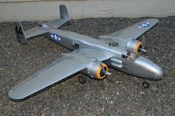
The completed model, ready for its maiden flight, came in at 24 ounces.
Drew flies on two Blue Wonder motors with plenty of power for scale flight and even some aerobatics. Despite its scale looks, this Mitchell is light enough that we have launched and recovered sorties on a T-ball field. At 24 ounces, the approach is at a brisk walk and the landings are greasy even for a kid. (Who am I kidding? He flies better than I!) I was so happy with his result that I built another for myself. To get his goat, I added retracts without servos, two 300 1,360 Kv motors, and three-blade 8 x 4 propellers! I also bashed mine into the stubby-nosed H model that brandished a 75mm artillery piece.
Conclusion
Drew has come a long way throughout the course of this project. In addition to picking up some CAD and building skills, he learned to solder, vacuum form, and to fly while we were building. Most importantly, he’s learned the value of these skills by applying them to new projects. He recently built and maidened a Shumate T-38 on his own. Not bad for a kid!Image
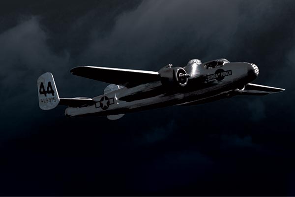
Drew is at the sticks after a hand launch. Removing the plug-in landing gear gives it a nicer look in the air and less drag.
I’m learning to let my son stand on his own feet now that I’ve seen what he is capable of. He has helped me appreciate anew the wonder of our hobby by viewing it through his eyes. So, the moral of this story is that, in addition to building an airplane, we have built memories that will last another generation. Now we just have to decide what we’re going to tackle next! —Paul Kohlmann [email protected]


Comments
Add new comment