


Skyshark RC 1/9th Scale Hawker Tempest Kit
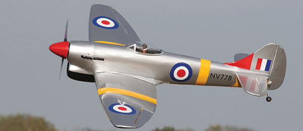
Written by George Kaplan Build this seldom-modeled warbird Product Review As seen in the February 2018 issue of Model Aviation.
Bonus Video
Specifications
Model type: Laser-cut kit Skill level: Intermediate/advanced builders and pilots Wingspan: 54 inches Airfoil: Semisymmetrical Length: 45 inches Weight: 8 pounds ready to fly Power system: .46 to .61 two-stroke (glow); .56 to .91 four-stroke (glow); .46 to .52 outrunner (electric) (review model: E-flite Power 52 motor; 80-amp ESC) Radio: Spektrum AR6600T receiver; a mix of servos; and a couple of servo extensions Price: $219.95Pluses
• Laser-cut plywood and balsa make up the entire airframe. • Fiberglass cowl, vacuum-formed canopy, wing fillets, and belly pan included. • 3.5-inch aluminum spinner also included. • A single, low-profile aileron servo is needed.Minuses
• Lightening holes are referenced and shown throughout the manual. None of the pieces included lightening holes or even holes to pass wiring through. I had to cut my own as needed. • 48-inch lengths of balsa are mentioned several times in the manual, but only 36-inch lengths were included. • If you’re not an experienced builder, you’ll find the concise wording in the manual to be lacking in spots because it’s assumed that the builder knows the correct way to accomplish several of the steps.Product Review
I love building kits. For me, it’s a relaxing way to enjoy our hobby and I love that when someone asks about one of my models, I can proudly say that I built it. There are plenty of great ARFs and RTFs out there (and I own several), but I love taking the time to figure out how things go together and learning new ways of construction. When I was offered the opportunity to review a kit—a real build-it-yourself-from-wood kit—I jumped at the chance. The kit is the Hawker Tempest Mk. V from Skyshark RC. This is one of many warbird kits that Skyshark has been producing for some time. Having never built a Skyshark kit, I was excited to give it a go. With the benefit of hindsight, let me say that this is not a beginner’s model. The construction techniques are not necessarily difficult, but having success with a kit like this requires quite a bit of previous kit-building experience. Also let me address that this model is not specifically designed to be electric powered. Skyshark suggested that the Tempest be electrified for this review so you’ll see several modifications/adaptations that are of my own design.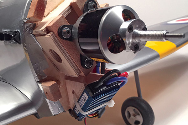
Here you can see part of the Tempest’s electric conversion. The author made this motor box and the angled ESC mount from spare plywood and hardwood stock that he had on hand.
The Tempest kit comes in an unassuming box. Inside is a variety of pieces, but not much in the way of hardware. It mostly contains various lengths, widths, strips, and sheets of balsa, plywood, and hardwoods. Some pieces that are used for wingtips and the rear of the fuselage are roughly shaped. Others, such as the wing ribs, formers, and control surfaces have been laser cut. The wood selection was quite good. The balsa was nice, straight, and easily bendable. There were a few places where the laser-cut balsa and plywood pieces weren’t cut all the way through, but that’s minor. Two surprises in the box were the inclusion of an extremely nice fiberglass cowling and a 3.5-inch aluminum spinner. Also included are several vacuum-formed pieces including the wing fairings, the belly pan, exhaust ports, and canopy. Rounding out the kit was a set of rolled plans and some hardware (fixed main gear and tailwheel struts, and a prebent joiner for the elevator halves). The rest of the necessary hardware is up to the builder. Some might frown on this, but most of us source out our own hardware, regardless of what comes in a kit.
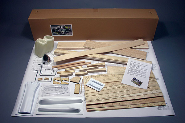
The Skyshark RC Tempest Hawker Mk. V kit includes a nice selection of wood, sheet, stick, and laser-cut pieces. It was a nice surprise to see the quality of the fiberglass cowl, vacuum-formed pieces, and the metal spinner.
In this case, you’re not paying for extra hardware that you probably would use, so that’s good. For this review, Du-Bro Products provided everything I asked for to complete the kit. The manual is not included in the kit. I needed to go online, download a copy from the Skyshark website, and print it. It’s 18 pages and shows a few pictures of the construction along the way. I had to read it quite carefully because many steps are succinctly worded. One more note on the wood: Several steps in the manual refer to 48-inch wood being provided, but only 36-inch wood is in the kit. Because of this difference in length, I was quite careful (and frugal) on how I used the wood. In several steps, I pieced a couple of smaller lengths together, especially in a non-load-critical situation. This allowed me to save the longest pieces possible for when needed.
Assembly
Construction starts with some simple steps such as building the horizontal stabilizer and vertical fin assemblies. The internal framework is sheeted on each side with 1/16 balsa. Next the rudder, elevator halves, and ailerons are built. Skyshark designed these control surfaces to maintain the look of ribs, just as on the full-scale Tempest. The assembly starts to ramp up in complexity with the center section of the wing. To start, you need to decide whether you’d like fixed or retractable gear. Depending on the direction you choose, the steps are different. Because Robart Mfg. supplied a set of electric retracts, RoboStruts, and the company’s great-looking 3.5-inch tires with aluminum hubs, I went the retractable route. The steps involved are straightforward. Everything is laser cut with the ribs fitting into the spars as called out on the plans. I had to do some trimming on the provided plywood retract mounts to allow the Robart retract mechanisms to fit, but nothing that a few minutes with my Dremel tool couldn’t solve. Robart’s RoboStruts are long and need to be cut to length, depending on the model. More trimming is needed to allow the gear to retract into the wing because a good portion of both W3 ribs have to be removed to clear the strut and wheels when retracted. Because the top of the W3 became so thin when doing this, I added some extra wood on both side of the rib for reinforcement.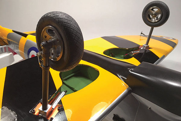
Robart’s RoboStruts and electric retracts were a good fit for the Tempest. They worked perfectly and their slower operating speed gives the model that extra bit of scalelike authenticity.
When it comes to creating wheel wells, you’re left to your own creativity. I found it odd that the manual instructs you to form these out of spare 1/16 sheeting; I’m not sure how anyone would have spare wood this early in the build! I temporarily installed the retracts, struts, and wheels, so that when they were retracted, I could use them as a template to build around. Leaving roughly a 1/2-inch gap, I carefully made each wheel well. Because the walls are made from such thin material and would be open to the elements, I also used the same 1/16 sheeting to build up support bracing for the well’s sheeting. After sanding the top surface, the center section has its top sheeting applied. Now preparations are made for the aileron linkage. As described in the manual, only a single servo is needed to run the pushrods to both ailerons. I’d recommend this system but you’ll need a low-profile servo. After another good sanding, the bottom of the center section is sheeted. Holes will have to be cut in the sheeting to reopen the wheel wells. Work now moves on to the outer wing panels. Each is built exactly the same, but mirroring each other. The laser-cut dihedral braces made it easy to properly angle the outer panels and assembly goes quickly. Some time is needed to correctly install the aileron bellcranks and pushrods because once they’re sheeted over, there’s no getting to them unless you cut into the wing. After sheeting the top and bottom and doing a bit of sanding, the wingtip blocks are added. Now a good overall sanding is needed to smooth and shape everything, especially the wingtips and leading edge (LE). The fuselage is next and it’s built in two halves starting with the bottom. Formers are glued in place over the center rails, but the next step brought things to a halt for a couple of days. The plywood wing saddle needs to be warped to match the contour of the fuselage. I created a 50/50 ammonia and water mixture and submerged the cradle pieces to soak. It took 24 hours of soaking to make the pieces pliable enough, then each piece was tightly wrapped around something round to form the piece to the rough shape. (I used an old baseball bat). It took about another day for the pieces to dry then I was ready to glue them in place along with the stringers. After the bottom is sheeted, the wing is positioned so that the LE dowel holes can be drilled. Then the top formers and stringers are installed, as well as the cockpit area and outer tubes for the pushrods. After the upper area is sheeted, everything is sanded and the firewall is glued to the front former. The firewall former is held in place by thin 1/16 sheeting and a handful of 1/4-inch square balsa strips. There is no plywood to distribute the load back through the cabin area, so this area could be a weak spot in a nose-over or ground loop. The wing is fitted back into the saddle, and the hole for the rear hold-down bolt is drilled and tapped. I left the wing in place to help align the stabilizer and vertical fin, which were the next steps. Once in place, blocks of wood are formed and placed around the joints to complete the fuselage shape. Next, the formed wing saddle and wing fillets were trimmed and glued into place. These took a lot of trial and adjustment to work correctly. A fair amount of filler was used to feather the shapes into the fuselage. Finishing the major construction, I sanded everything well and other than mounting the cowl, that’s about as far as the manual takes you. There are a few tips for the rest of the steps, but remember when I mentioned that you should be an experienced builder to tackle the Tempest? Here’s where that comes in. First, I had to work out how to incorporate the power system. Knowing that the Tempest would need nose weight, I choose to mount the Power .52 motor on heavier hardwood blocks to get the spacing I needed. Dry-fitting the cowling in place, I measured, cut, and designed my own motor mount. After this was done, I could drill the holes to mount the cowl. I choose to power the Tempest with a big 6s, 5,000 mAh LiPo battery pack, positioned as close to the firewall as possible. This meant designing a battery tray. It involved cutting away and opening up holes in the formers so the battery could slide in. I could have engineered an elaborate external hatch, but it was simply easier to mount the battery into the fuselage by taking off the wing.
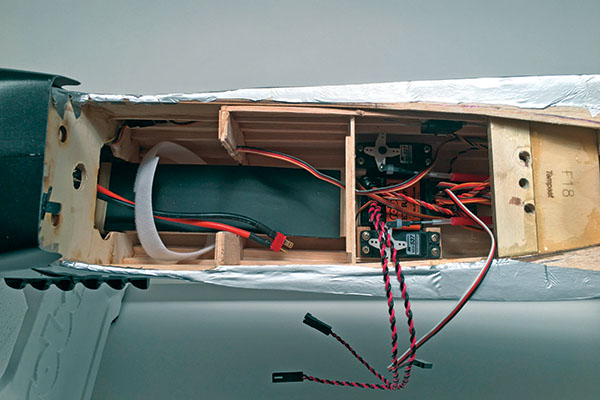
Inside the Tempest’s fuselage is plenty of room for the radio installation and even the large LiPo battery pack needed for electric power. The author modified the front formers and designed the battery tray you see here.
Hardwood is provided to mount the servos, but it’s up to the builder to work out exactly how to do that. After everything is in place, you can’t hinge the surfaces because you’d be cutting into 1/16-inch thick wood and that won’t hold. I marked where the hinges would be on each of the control surfaces and built up the area between the ribs on each side with additional balsa to give a minimum of 3/16-inch surface for the hinges and glue to grab. When attaching the belly pan, I’ve learned from experience that a thin, formed piece of that size needs some support underneath it. If it is not supported, simply resting the wing on a flat surface could deform the piece enough so it warps, cracks, or breaks free. I used several pieces of scrap balsa to help build a supporting “spine” for the belly pan. When I was finished, I covered the entire airframe with UltraCote. I chose UltraCote because the covering scheme I chose required a lot of overlapping colors and UltraCote is great for that. The only paint I used was some gloss black on the belly pan and the lower part of the cowl, a bit of aluminum for the top of the cowl, and red for the spinner. I was pleased to see that my modifications allowed the Tempest to balance on the center of gravity (CG) without any additional changes. Its weight was on the upper end of the recommendations at 8 pounds ready to fly, but that’s to be expected in an electric conversion.
Flying
The way the Tempest is designed, the CG is practically over the wheels, and a lot of weight is needed in the nose to get the CG right. Taxiing with such a lightweight tail is extremely tricky. I had no luck taxiing through the grass to the runway, so I placed the Tempest on the runway for its maiden flight, but that maiden flight didn’t happen right away. After several practice taxi runs, I lined up for the first takeoff and was too slow with the elevator. The Tempest came right over on its nose when I added power and there went the new spinner and there was a bit of scraping on the cowl. I reached out to Dave Brown Products, and the company was able to provide me with a similar spinner. After things were patched and painted, it was back to the field for another try. This time I was more successful. Learning from my first attempt, I kept a considerable amount of up-elevator in until the tail started flying. I backed off a little and the Tempest was finally in the air. At higher speeds, you can fly big, smooth maneuvers, taking up a lot of sky, just as the full-scale Tempest would have done—big loops, nice graceful barrel rolls, Immelmann turns, and more. The Tempest doesn’t have unlimited vertical power or hovering ability, nor should it. I experimented with the Tempest’s slow flight characteristics at three mistakes high, and found it can tip stall if you let it get too slow. Flaps would certainly help, but because it doesn’t have them, keep the speed up on slower flybys and landing approaches. Fortunately, I had set my timer because before I knew it, it was time to work on landing approaches. I’d lost track of time by tearing holes in the sky! The first few landing attempts were too quick for my taste. It took me some time to figure out how to set the Tempest down. Remember, it’s a little on the heavy side at 8 pounds and does not have flaps, so be sure to practice while you still have power.Conclusion
The Skyshark RC 1/9th Scale Hawker Tempest Mk. V is a great build, but it is certainly not for an inexperienced builder. It’s tricky when taxiing, but quite enjoyable in the air. The Power .52 and 6S 5,000 mAh LiPo battery pack provided more than enough power and gave me flight times of close to 10 minutes—a little longer if I just cruised.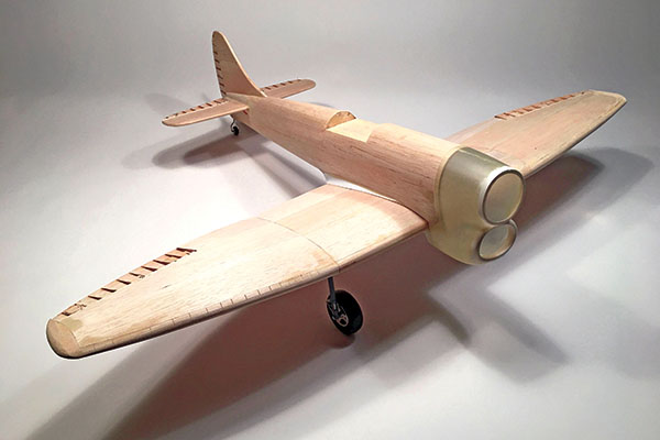
Building any kit to this point will give you immense satisfaction. Skyshark left the control surfaces unsheeted to give it a ribbed look after covering.
—George Kaplan [email protected]
Manufacturer/Distributor:
Skyshark RC (239) 800-1941 www.skysharkrc.comSources:
Tempest manual www.skysharkrc.com/Downloads/2017_Tempest_Instructions.pdf Robart Mfg. (630) 584-7616 www.robart.com E-flite (800) 338-4639 www.e-fliterc.com Du-Bro Products (800) 848-9411 www.dubro.com Dave Brown Products (513) 738-1576 www.dbproducts.comThis Month's Issue

Join the AMA
![]()


1 comments
Skyshark Hawker Tempest Kit
Add new comment