


Retro RC The Saucerus RC
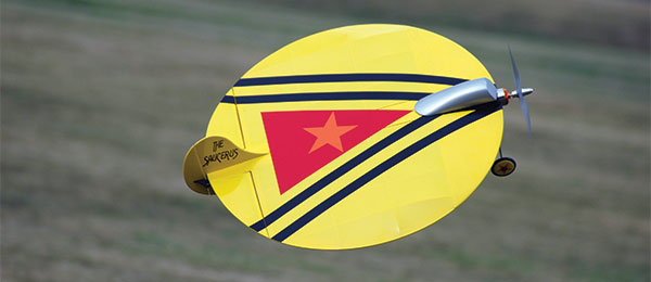
Written by Joe Hass A CL-inspired flying saucer Product review Photos by the author Read the full product review in the October issue of Model Aviation.
Specifications:
Model type: Laser-cut kit Skill level: Intermediate Wingspan: 19 inches Wing area: 283 square inches Length: 21 inches Weight: 17 ounces Construction: Balsa and light plywood Street price: $89.98Test-model details:
Motor used: Turnigy 2822/14 1,450 Kv brushless electric outrunner Speed controller: Turnigy 20-amp Servos: Three Hitec HS-55 Battery: Glacier three-cell 800 mAh LiPo Propeller: APC 7 x 4 Radio system: Tactic TA624 receiver; Tactic transmitter Ready-to-fly weight: 17 ounces Flight duration: 5 to 10 minutesPluses:
• Interlocking laser-cut parts make building easy. • Unusual configuration. • Incredibly strong. • Can be hand launched similar to a Frisbee.Minus:
• Requires significant nose weight.Bonus video:
Product review
Retro RC has an enviable history of reincarnating vintage designs into practical, enjoyable, easily built aircraft. The company has done it again with The Saucerus RC. The original design dates back to a 1953 George Harris Control Line (CL) model called the Sassy Saucer. Modern laser cutting and a great updated design make this an easy project. This review is slightly unusual in that it is based on a production prototype kit. I didn’t have formal instructions. I did have plans, some build pictures, and most importantly, access to designer Mark Freeland, who lives nearby. Start by reviewing the parts layout on the laser-cut wood and the plans. I found it helpful to either leave the pieces until they are needed or mark them for later identification. A couple of things can be done early and allowed to dry. The lower cowl is formed by wetting the piece and wrapping it around something that has roughly a 1-inch diameter. Form the pieces while keeping in mind the built-in right thrust. The wheels are built up on a drill bit. I prefer to use a slower-drying adhesive to make sure that every surface is wetted. Avoid getting adhesive on the outer surface of the balsa disk because it will be difficult to sand to shape. After the wheel assembly is thoroughly dry, simply chuck the drill bit into your drill or drill press and sand a smooth contour to the balsa disk. I used 220-grit sandpaper to avoid removing too much material.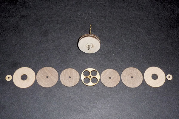
Nine pieces of plywood and balsa form the wheels. Use a drill as a guide to hold everything in alignment. The drill then becomes the spindle to shape the balsa end caps.
Assembly
The saucer is composed of interlocking ribs running front to back and spars running left to right. Follow the plans and begin interlocking the ribs and spars. The ESC tray interlocks between two ribs and two spars on the right side. Don’t glue anything yet. Pay special attention to the orientation of each piece of the outer ring. You should have five separate sections. H1 and H8 stay separate, H2 and H3 are glued together, H4 and H5 are glued together, and H6 and H7 are glued together. These subassemblies slide into the perimeter slots in the ribs and spars. The sub ribs associated with the elevons should be installed when you are sliding in the outer ring pieces. The most important part of the process is properly aligning all of these pieces. Prop up the outer ring. I used some scrap strip balsa that was cut to 1-inch lengths. Whatever you have handy will work, but support the entire perimeter and add weights to hold everything in place. Now sight down each rib and spar to make sure they are perfectly straight. Using a straightedge is preferred, especially on S5 and S6 because they serve as the hinge line for the elevons. Sand, trim, and adjust to make sure everything is perfectly straight. Use the control horns to adjust the spacing of the EVR sub ribs and to create a slot for the elevons. Use the vertical fin F3 to confirm that CR1 and CR2 are truly vertical and spaced correctly. All of this alignment will pay off later, so take your time. There are laser-cut slots for the CA hinges on the elevons. I positioned the CA hinges in the slots (without gluing them) to maintain alignment. You can also use a #11 X-Acto blade to hold them. When you are satisfied that everything is straight and vertical, begin at the center with a few drops of thin CA glue at each joint. Work your way around the airframe, rechecking alignment as you go. Add S5a and S6a to the top and bottom. Add the precut sheeting WS8 for the fin area. After seeing some of the prototype aircraft, I decided to add sheeting between EVR and CR2 to create more contact area for the covering. You can also add additional ribs. The motor mount, landing gear mount, battery box, and receiver mount are lightweight plywood assemblies. Pay special attention to the left and right markings on each piece. I decided to not laminate the landing gear in place to make covering easier. This assembly slides between R4 and R5. The leading edge (LE) sheeting is precut and assembled before attaching it to the wing. Carefully check the fit. Because of the complex curve, I found that it was helpful to wet the outer surface with ammonia to help bend the sheeting. Start at the center section and work outward, gluing only a small section at a time. You will have to trim each rib for the best fit. Work slowly. I used thin CA glue to attach the sheeting.Servo, Receiver Hatch, and Fin
The servo tray is designed for Hitec HS-55 servos. Unlike everything else in the kit, there is no laser-cut interlocking location for the servo tray. This is deliberate to take into account a variety of servos. There is also no hard point for the servo splines to pass through the covering. This is also by design. Position the servo tray with the servo splines slightly above the expected location of the covering. I’ll have more specifics about handling this when we detail the covering. The receiver hatch is composed of seven balsa pieces, plus the magnet. The matching hatch support is installed on top of the floor in the receiver bay. The receiver can be suspended with rubber bands, on a scrap balsa floor, or allowed to float in the opening as I did with it. The lower fin is assembled with a balsa core, plywood stiffeners, and plywood doublers for the plywood tail wheel location. An eyelet is used for the wheel axle. The canopy is made up of multiple balsa pieces that are sanded to shape. Make sure the plywood floor and magnets are correctly oriented to take into account the built-in right thrust and magnet polarity. Next, finely sand everything before separating the elevons from the wing. A razor blade or #11 blade works best. After the elevons are separated, carefully sand in the bevel in the LE of each elevon. Be careful at the pointed end because it will sand quickly. You should now have a group of completed assemblies. I painted the wheels and the canopy. A few coats of primer and some sanding will make them ready for your finish colors.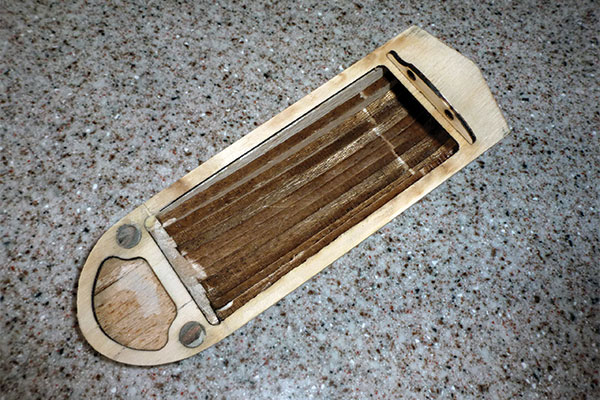
The canopy is made from multiple pieces of laser-cut balsa and sanded to shape. Attach the balsa to the plywood floor before sanding.
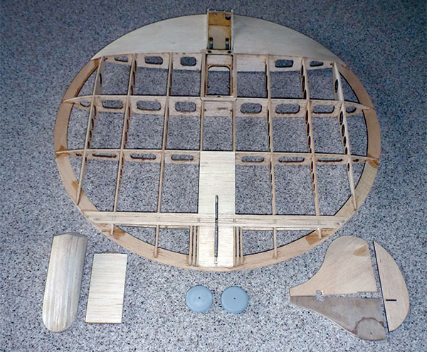
This shows the completed assemblies before covering. The wheels have been primed.
Servos and Covering
Let’s get back to the servos and covering. Although you can add some wood to create a hard point for covering, Mark suggested a simple solution. Cut your covering larger than the diameter so you have plenty to hold on to. Center the covering and then push firmly over the exposed splines, slightly denting the covering. Take a soldering pencil and carefully burn a hole at the location of each spline. Now position the covering over the servos with the splines in the three holes. Use a covering iron to attach the covering around the servo bay. Gently tighten the covering in the servo bay. Proceed to cover the rest of the bottom of the wing, wrapping the covering completely over the edge of the outer ring. Cover the top, allowing roughly 1/8 inch of covering to fold around the bottom of the outer ring. Attach the upper and lower fins with thin CA glue. Hinge the rudder and elevons with thin strips of CA hinge material. The landing gear and final motor mount were attached with 5-minute epoxy. The ESC slides into the compartment in the wing. The motor is attached with four screws. The wheels are held in place with four laser-cut plywood disks. Use gap-filling CA adhesive to glue the disks to the wire. Decorate your The Saucerus RC with an eye toward easy visual recognition. You need to be able to see it! Bend a little bit of tow-in on the landing gear to aid in tracking on the ground. Make absolutely sure that the elevons move exactly the same amount in each direction for both the aileron and elevator. I set the exponential at 30% for high rate and at 20% for the low rate. So far I have not switched to low rates.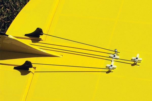
Control horns and pushrods have been installed. The kit includes a complete hardware package.
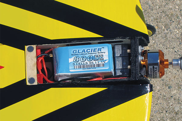
This depicts the battery compartment and motor mount. The front of the canopy attaches to the pins and is held in place with magnets.
Balancing
Balance is hypercritical. The center of gravity (CG) should start out at the rear edge of the LE sheeting and no farther back. For the first flights, I added 2.25 ounces of lead directly behind the motor mount. If I were to do it again, I would not attach the lower cowl sheeting before checking the balance because this area is a great place to put any needed lead.Flying
My first flights were emotional. The machine was unpredictable. Its worst characteristic was a tendency to tuck under from level flight. The second landing was more of an arrival that bent the landing gear and broke the wheels. I added another 1/2 ounce to the nose, bringing the added weight to 2.75 ounces. The third and fourth flights were simply amazing! I experienced no bad tendencies. After talking with Mark, I added some aileron-to-rudder mix. It made turning easier, but rolls were more like corkscrews. I have moved the aileron-to-rudder mix to a switch to be able to turn it off in flight. So what should you expect on your first flights? If possible, find a smooth area for your first takeoff. Advance the throttle with a touch of down-elevator to get the tail up. That will get the rudder working (remember there is no steerable tail wheel). It will accelerate quickly and with only a little up-elevator, you will have The Saucerus RC airborne. At full throttle, The Saucerus RC is extremely fast, so expect to quickly get the throttle to midrange as you check the trims. With a 1:1 aspect ratio, you will be working and coordinating the controls, yet at slow speed and high angle-of-attack, flight is easy and stable. Expect to work the throttle to get maximum flight performance and enjoyment. It will turn well with only the rudder. Rolls with the mix turned off are axial. Loops, Immelmanns, Cuban 8s, and Spilt S maneuvers are all easy. Inverted flight needs virtually no down-elevator. It is plenty fast, so keep the throttle at midrange for most of your flying. Landings are easy. Simply keep adding up-elevator until touchdown. The Saucerus RC can be flown in small areas, including indoor soccer fields. The Saucerus RC will draw attention wherever you go. It is small enough to fit in a subcompact car. Make sure that you have your model decorated in such a way to be able to maintain orientation. The CG is critical, so make sure it is correct before your first flight. A gyro stabilization system could be considered, but is not required. This is a fun project and it is extremely durable. Building is easy with all of the laser-cut parts. You can get quite creative with the color scheme. You should enjoy building and flying The Saucerus RC from Retro RC. —Joe Hass [email protected]Manufacturer/Distributor:
Retro RC (248) 212-9666 www.retrorc.us.comSources:
Tactic (800) 637-7660 www.tacticrc.com Hitec/Multiplex (858) 748-6948 www.hitecrcd.com Buddy RC (614) 824-7250 www.buddyrc.com Turnigy www.turnigy.comThis Month's Issue

Join the AMA
![]()


Add new comment