


Reading Plans
Written by Paul Kohlmann
Learn how to correctly read your plans.
Featured in the Construction Series in Model Aviation May 2015.
One of the best parts of writing this series of articles has been discussing modeling with some notable builders in our hobby. Pat Tritle is one of these people, and when I asked what topics he would like to see covered for new builders, his reply was immediate. He suggested a piece on how to read plans.
This led to some interesting discussion on how often problems with a build can be avoided by closely reviewing the plans before the building starts. It is often useful to study all of the notes and views and then “prebuild” the project in your mind.
This article will cover the basics of how to read a technical drawing. It will focus on the “correct” methods that drafters normally use in industry, but it is important to recognize that model designers often work to a much looser standard.
Title Block and Notes
This should be the builder’s first stop. Adding notes to a drawing can be time consuming. With that in mind, you won’t find many notes on plans that the designer didn’t think would be important to you.
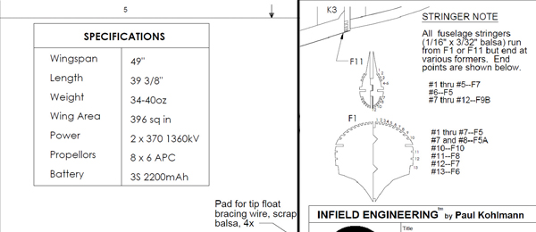
At a minimum, a title block with the subject, designer’s name, and date should be located at the lower right hand corner. The date is handy because the equipment available at the time the plans were drawn probably influenced the construction method. Some designs withstand the test of time while others—well, not so much.
A designer often provides additional blocks of notes. One common example is a specification table that lists the model’s wingspan, length, and expected weight. Wing area and projected wing loading may also be provided.
The specifications may include the power system used by the designer. This is useful because it gives the builder an idea of the designer’s goals. If the plans call out a 370-size motor, then you will probably need substantial modification if your goal is to use that spare Power 15 in your drawer. That’s not to say that you are stuck with whatever the designer used.
For many, straying from the plans to create something new is part of the reward of scratch building. Just be aware that a modification that significantly changes the model’s power or weight is likely to require modification to the airframe.
Designers often include assembly instructions on the plans when they spot potential problems. By calling out an assembly order, the designer may help you avoid a fit or accessibility problem. Again, the designer’s notes aren’t gospel, but consider the possible consequences before you choose to go your own way.
One of the most important notes on the plans is the placement of the center of gravity (CG). By marking this on the plans, the designer is telling you that this aircraft will fly when it is balanced as shown. Disregarding this is the most common source of poor performance. It is possible that you will fine tune the CG to better suit your flying style, but this is best done after the maiden flight.
Finally, a bill of materials (BOM) is handy. When fully developed, the BOM is the complete shopping list for wood, electronics, hardware, and power systems for your project. The BOM is often partial because designers understand that builders normally use the hardware and electronics that they are familiar with.
Drawing Views
Drafters have traditionally used the “glass box” to characterize the standard views on their drawings. These standard views are arranged in a specific order so that fabricators can rapidly construct a 3-D mental image of the subject. Adhering to these rules avoids problems such as building the mirror image of the intended part.
Engineering drawings of this type are commonly called three-views, although more or fewer views can be incorporated. The basic three-view layout will show the front view, the top view, and whichever side presents more detail.
Model plans often use a looser standard. The main reason for the departure is that the views most needed by builders are the ones that they will be building directly on top of. A side view of the fuselage is much more useful than a head-on view. The side view gives the builder the overall size and appearance of the subject, as well as the position of critical components such as formers. A similar top view of the wing provides the correct angles of ribs, spars, and other elements. Separate views for the layout of the tail group parts are also handy.
Fitting all of these “building” views onto reasonably sized plans normally requires the builder to abandon the glass-box arrangement. The views may be rotated and moved around to maximize clarity within the allotted real estate.
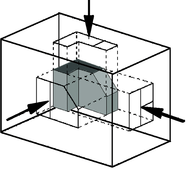
The "glass box" encloses the subject of the drawing.


When the box is unfolded, each pane provides a specific view.
Special Views
Building an airplane often requires more than the limited number of views previously described. Two types of special views are worth mentioning. The first is the detail view.
The detail view focuses into a specific area by stripping away other components, by changing the viewing angle, or both. The detail view can be either two-dimensional (2-D) or three-dimensional (3-D).
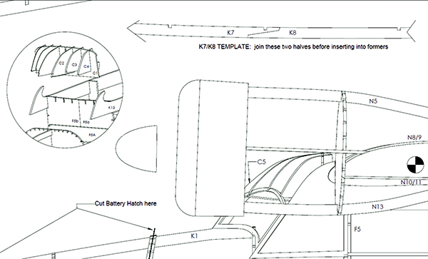
Detail views may be 3-D such as the inset on the left, or 2-D like the setup template to the right.
A 2-D detail view may show the alignment of certain parts, such as two keel halves that must be preassembled over the plans before installation. A 3-D example might show the arrangement of an assembly of many parts that is tough to envision from the 2-D plans views.
As the name suggests, detail views show only part of the picture. For this reason, they must be isolated in some way. 2-D details are often cut off by a jagged line. 3-D details might be enclosed within a circle or fade away at the edges.
An exploded view is often used to show how a collection of parts is fitted together. This view is normally a 3-D representation.
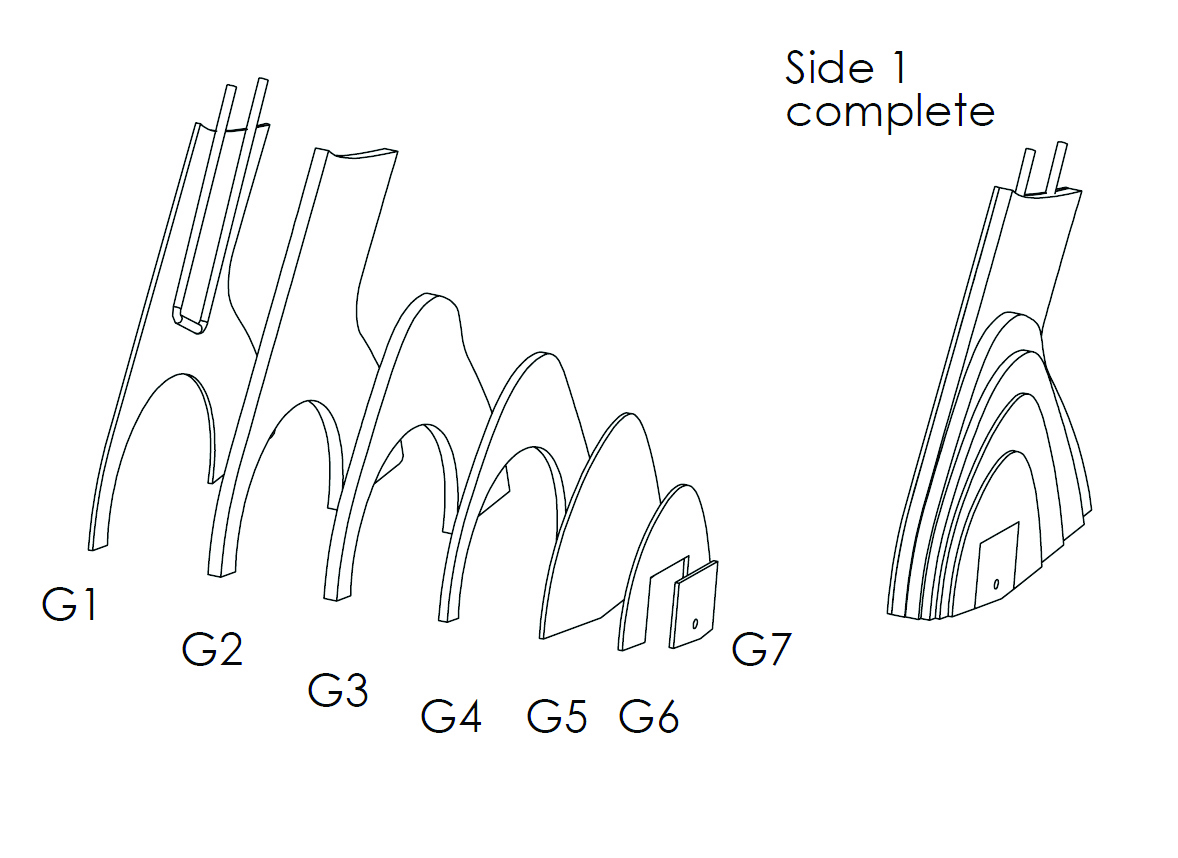
An exploded view is used to show the relationship between parts of a group.
Line Types
The type of line used by a drafter is also subject to rules. Each type is selected for a specific purpose. The most common line types are:
• Visible: This heavy, solid line is used to show the feature outlines of parts that are visible from the angle shown.
• Hidden: This medium, regularly dashed line shows the positions of features that are internal or behind the features that are visible from the angle shown.
• Center: This light line is broken into alternating long and short sections. It is used to show the axes of holes and shafts, and the centers of circular features.
• Section: Collections of these light lines are used to show cut surfaces as hatched or cross-hatched areas.
• Dimension: Light lines that flag the points measured by a dimension. Lightweight arrows are used perpendicular to the dimension lines to bracket the numerical dimension.
• Break: May be heavy or light, depending on the style. These lines enclose a portion of a drawing that has been cut away, like a detail view.
As with views, model designers may take some liberties with the rules on lines. Usually these departures are limited to using a fancy line type to draw attention to a feature.
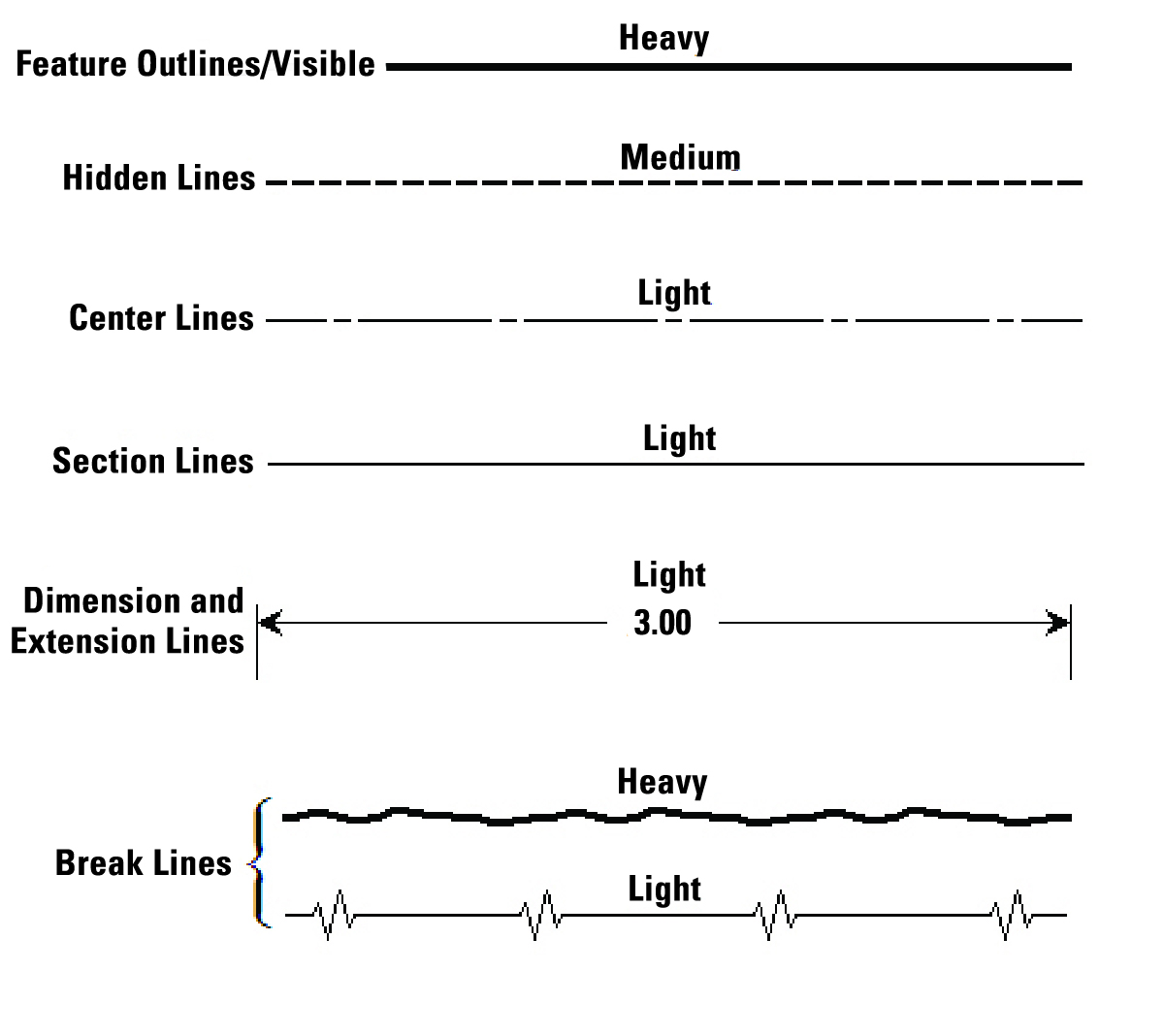
Each of these line types has a specific purpose in a technical drawing.
Wrapping It Up
Reading a bona fide blueprint can require a degree of skill and knowledge. Fortunately, most model plans are simple forms of technical drawings.
Even with that noted, everything on the plans was put there for a reason. Taking the time to review the plans until you clearly understand them before the build starts is the best way to avoid problems with the build.
The next time we meet, we’ll discuss some detailing techniques that can help transform your project from functional to fantastic.
—Paul Kohlmann [email protected]
SOURCES:
Grumman Goose Plans www.modelaviation.com/goose
This Month's Issue

Join the AMA
![]()


4 comments
how to read plans
How to read plans
Reading Plans
Model aircraft construction
Add new comment