


Arado Ar.396
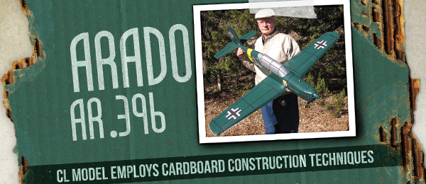
CL model employees cardboard construction techniques Featured in the September 2014 issue of Model Aviation Construction article, photos, and plans by Chuck Felton
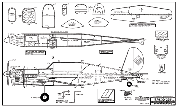
Order Plans from AMA Plans Service
|
|
 |

Specifications
Type: CL Scale Wingspan: 60 inches Length: 49 inches Wing area: 541 square inches Weight: 74 ounces Wing loading: 19.7 ounces per square foot Power system: .40 to .50 sized glow motor or equivalent Construction: Primarily cardboard
Arado History and Setup
The Arado Ar.96 was a low-wing, single-engine aircraft of metal construction, which became the Luftwaffe’s standard advanced trainer during World War II. However, as the war progressed, it was decided to redesign the Ar.96, the chief goal being to save metal. The result was the Arado Ar.396, which was constructed primarily from wood. These aircraft were to be built in factories in occupied France, but the subsequent course of the war made that impossible, and production was moved to Czechoslovakia. Only a few aircraft were built by war’s end and none were pressed into service. After the war, SIPA built roughly 200 in France which were used for training and as counterinsurgency aircraft in North Africa. The latter aircraft were fitted with wing racks for carrying light bombs and rockets. The Arado Ar.396 model is simple to construct and inexpensive. It uses 1/8-inch corrugated cardboard as the primary building material, which greatly reduces building time and cost. The design makes use of cardboard’s unique features in that it can be used in large sections and folded. Each wing panel is built from a single piece of cardboard scored and folded at the LE with cardboard ribs and a single spar. The tail surfaces and fuselage are primarily cardboard with little internal bracing required. The result is a low-cost, fast-building model that has good, scalelike appearance and can take plenty of punishment at the flying field. Cardboard varies in weight, but any 1/8-inch corrugated cardboard will do. Sources of this material include box manufactures and local shopping centers where you can find stacks of discarded boxes. Look for cardboard with brown paper on one side and a white-finished Kraft paper on the other side. The white paper on the outside of the model results in a smoother finish and a neater appearance. The method of folding the cardboard and using gummed paper tape to seal the joints and exposed corrugation is explained in the construction hints. The model has a 60-inch wingspan and a length of 49 inches. The bottom of the airfoil is flat with a curved upper surface, created by the scoring and folding technique employed. A .40- to .50-size engine can be used. My model is powered by a .40 engine and has a fully fueled flying weight of 74 ounces. This weight, combined with the 541-square-inch wing area, results in a wing loading of 19.7 ounces per square foot.
Construction
Empennage The fin, rudder, stabilizer, and elevators are each made from two pieces of 1/8-inch cardboard laminated together cross-grain to give 1/4-inch-thick surfaces. Add a 1/8 x 1/4-inch balsa strip to the fin’s LE and round it off. Add 1/8 x 1/4-inch balsa strips to the stabilizer’s LEs and TEs and the elevator’s LE and round them off. Seal all raw edges with gummed paper tape. Hinge the elevators to the stabilizer with flex hinges at four places.
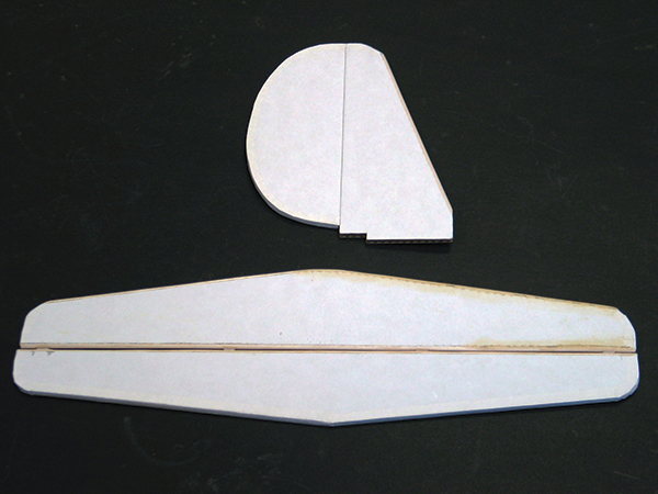
The empennage and elevator hinge line LEs are capped with 1/8 x 1/4 balsa strips and rounded off. The elevator is joined to the stabilizer with flexible nylon hinges at four places.
Wing Make the three wing spar sections (one center and two outboard) from 1/4-inch balsa capped with 1/4-square spruce strips. Join the three spar segments with 1/8-inch plywood joiners, front and back, making sure to maintain the correct dihedral. Glue the 1/8-inch plywood gear mounts into the bottom of the center wing panel. Glue the wing spar into the center wing panel. The three center wing ribs (W1) are then added. The ribs at the plywood spar joiners are shortened by 1/8 inch to account for the joiner thickness. Add a cardboard doubler over each plywood gear mount. Apply glue to the top of the wing spar, the top of the ribs, and the wing’s TE. Fold the center top wing surface down and pin it securely in place until dry. Glue the right side spar into the bottom of the right-hand outboard wing panel. Add cardboard ribs W1 through W6. Glue a 1-ounce weight to the right wingtip. Build the left outboard wing panel in a similar fashion. Add the balsa tips to the wing and sand them to shape. Make a line guide from 1/8-inch plywood. Cut a slot in the left wing’s balsa tip and glue the line guide in place. Cover the TE and all seams with gummed paper tape.

The spar is glued to the bottom center section and cardboard ribs are added. Note the 1/8-plywood spar joiners at dihedral breaks and plywood gear mount inserts.
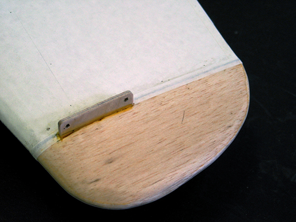
The top wing surfaces are folded down and glued in place. The balsa wingtip is made from 1/2-inch sheet with 1/8 plywood line guide. Paper tape covers the seam between the balsa wingtip and cardboard wing.
Fuselage The flat fuselage sides are outlined with a triangular symbol on the drawing. Line the upper and lower edges of each fuselage side with 1/8 x 1/4-inch balsa strips, as shown in the fuselage side view. The strips are recessed 1/8 inch from the fuselage edges. Bevel the strips at the aft end of the fuselage so that the cardboard sides will come together. Add cardboard supports to each fuselage side below the bellcrank and above the fuel tank. Make firewall A from 1/4-inch plywood. Locate the mounting holes for the KM40 motor mount on the face of firewall A. Drill a hole in it for a fuel-tubing exit. Drill two holes in firewall A and install blind mounting nuts on the back side. These holes must align with the holes in C1 and are used to attach the removable cowl section. Glue firewall A to the right side of the fuselage, making sure it is perpendicular to the fuselage side. When dry, glue the left side of the fuselage to firewall A. Attach the fuel tank to the 1/8-inch plywood support with rubber bands. Make a pushrod from 3/32-inch wire and 1/4-inch square spruce and attach it to the bellcrank along with the leadout wires. Install the tank and bellcrank assemblies by gluing the plywood supports to the cardboard supports on the insides of the fuselage. Glue the fuselage sides together at the tail. Glue F1 and F2 in place to cover the top fuselage. Be sure to bring the fuel tubing fill and overflow lines out during covering operations. Cover the bottom fuselage with F3 through F6. Note the gap between F5 and F6 for the 1/8-inch plywood tail wheel support. Glue the two G formers to the bottom forward fuselage, add a 1/8 x 1/4-inch balsa stringer down the centerline and cover with decking piece D4. Add fuselage formers B and C to the top forward fuselage. Add a balsa stringer down the centerline and cover with decking piece D1. Add the three D formers to the top center fuselage, add a balsa stringer, and cover with decking piece D2. Glue formers D, E, and F in place to the top aft fuselage area, add a centerline balsa stringer, and cover with decking piece D3. Complete the forward cockpit windshield by gluing W1 in place. W1 is made from thin manila folder-type cardboard with a 1/8 x 1/4-inch balsa strip glued down the centerline for support. The cowl is built up from 1/2-inch balsa sheet and carved to shape. The top half is glued to the model, while the bottom half is removable. The removable bottom half of the cowl has a 1/8-inch plywood C1 former glued to the back. Remember, the two holes in C1 must align with the blind nuts in the firewall A. Sand, carve, and hollow the cowl to shape. Test fit the engine in the cowl and drill mounting holes. Use a shaft extension to ensure adequate spinner clearance. Cut holes in the cowl block for the cylinder head, exhaust, and needle valve. Apply epoxy to the inside of the cowl and front of firewall. Glue the horizontal stabilizer to the fuselage. When dry, glue 1/2-inch triangular pieces to the underside of the stabilizer at the fuselage intersection for added strength. Glue the rudder to the fin with the TE offset 1/2 inch to the outside of the flying circle and glue in place. Add carved balsa fairings on each side of the fin to complete the aft fuselage. Glue the wing to the fuselage. Make each main gear from 5/32-inch diameter wire as shown. The pieces are attached to the mounting plates in the wing with nylon gear clips. Bend the tail wheel strut from 3/32-inch wire as shown, place on the plywood support, wrap with nylon thread, smear with glue, and mount in the bottom aft fuselage cutout between F5 and F6. Slip black fuel tubing over the main and tail gear wire for better definition. Adding a couple of drops of oil inside the tubing first will make this much easier.
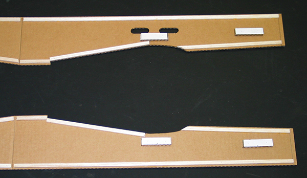
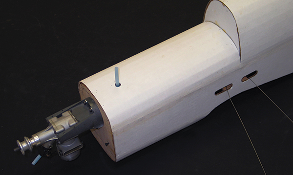
Flat fuselage sides are lined with balsa strips recessed 1/8 inch and have cardboard supports for the bellcrank and fuel tank plywood mounts. Note the cutouts for flying wires.
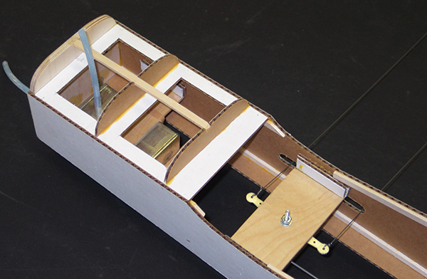
The fuselage’s forward bottom section has formers and a centerline balsa stringer ready for deck covering. Cutouts help reduce weight. The pushrod is made from 1/4-inch square spruce.
The completed forward bottom section is shown. Uneven seams are later cleaned up with strips of gummed paper tape.
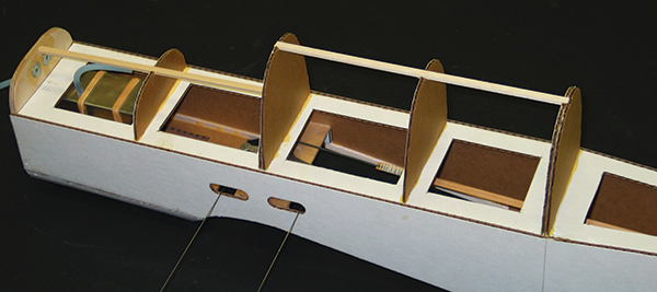
Cardboard bulkheads, held with a single centerline balsa stringer, are added to top fuselage. Be sure to bring the fuel tubing lines out during all covering operations.
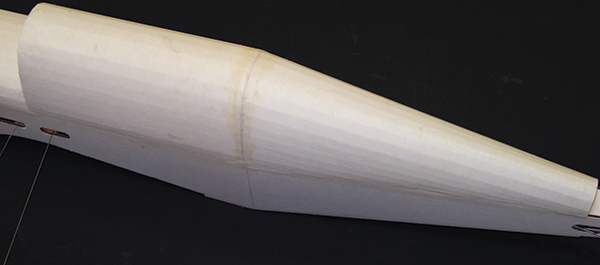
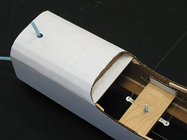
Scored and folded top decking pieces are glued over the cardboard formers. The seams have already been covered with gummed paper tape.
The forward fuselage is ready for the balsa cowl. The front windshield, piece W1, is made from thin, manila-folder cardboard.
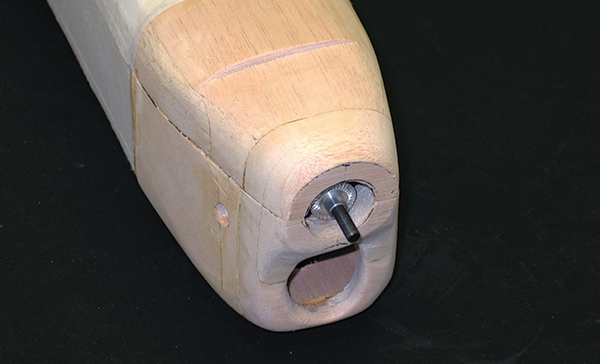
The cowl’s front nose block has one circular and one oblong cutout. I always use a 1/2-inch engine shaft extension for more clearance between my fingers and the propeller.
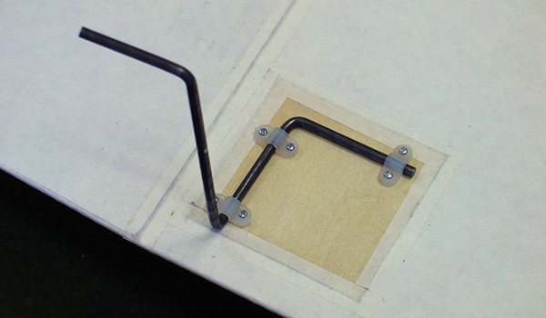
The main landing gear is 5/32-inch wire attached to plywood mounting plates in the wing bottom using three nylon gear clips.
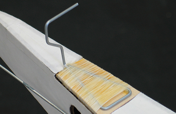
The tail gear strut is bent to shape from 3/32-inch wire, laid on its 1/8-plywood mounting plate, wrapped with nylon thread, smeared with glue, and glued into fuselage cutout.
Finishing Apply a coat of sanding sealer to all of the model’s balsa parts and sand smooth. Give the cardboard sections two coats of clear dope, sanding lightly after each coat with 400-grit sandpaper. Follow with two coats of color. The color scheme I used for my model is dark green on the upper surfaces and light blue for the lower surfaces. The patterns for the aluminum MonoKote pieces used to simulate the front and aft cockpit windows are shown on the fuselage drawing. The center section canopy is not shown because it is a simple rectangular section. Apply the simulated windows to the cockpit areas and outline them with black MonoKote strips. The striping, lettering, and insignia were made from MonoKote or designs developed in drawing program ModelCAD 3000 and printed on Avery sticky labels (#8165) with an inkjet printer.
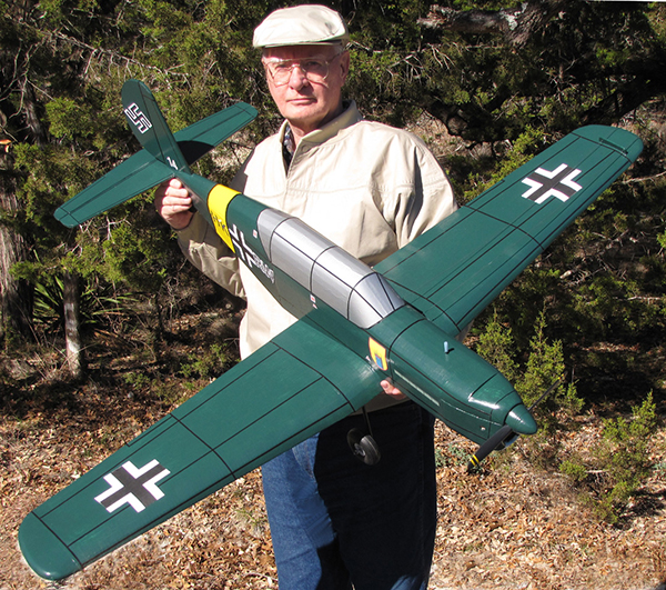
The author displays the completed Arado Ar.396. Cardboard construction is simple and inexpensive.
Final Assembly Pass the leadout wires through the wingtip line guide and tie them off. Attach the nylon control horn to the elevator and hook up the pushrod. Attach 3-inch diameter wheels to the main gear and a 13/4-inch diameter wheel to the tail gear. Add a 9 x 6 propeller and a 2-inch spinner to the engine and your aircraft is complete. Be sure to balance the model at the point shown on the plans. If you have any comments, suggestions, or questions concerning the cardboard Arado Ar.396, please don’t hesitate to contact me or add a comment below. —Chuck Felton
Construction Tips
- Before you begin building, take a look at these special tips for working with cardboard.
- Adhesive: Water-based glue, such as white glue or Titebond, is recommended. Contact cement is not recommended, because parts cannot be shifted when gluing surfaces.
- Folding: Scoring the fold lines is done with a screening tool available at any hardware store. It consists of a handle with a 11/2-inch radius wheel at one end, which is run along a metal straightedge on the fold line.
- Finishing: Cardboard gives a solid surface with no open areas to cover and is nonporous. The easiest finishing method is to give it two coats of clear dope, sanding lightly between coats using 400 grit sandpaper, followed by two coats of color dope. A wide variety of finishing materials can be used on the cardboard including coverings such as Solarfilm, MonoKote, and vinyl paper. With any of these, it is recommended that the surface not be doped, to result in a better bond.
- Paper tape: All seams, joints, and exposed edges of the model are covered with strips of gummed paper tape. Obtain a 1-inch-wide roll from a stationary store. Simply cut a thin strip to length, dip it in water, and smooth it over the seam.
- Construction: Being sure to note the direction of the corrugations when cutting out the cardboard parts. Score and fold cardboard parts as indicated on the plans.
AMA Plans Service (800) 435-9262, ext. 507 www.modelaircraft.org/plans.aspx Chuck Felton’s website www.feltondesignanddata.com
This Month's Issue
Join the AMA
![]()


Add new comment