


Glastonbury Meadowlark

Download plans for the Glastonbury Meadowlark. Article, plans, instructions, and photos by Dennis Norman. Online exclusive bonus content from the December 2013 issue.
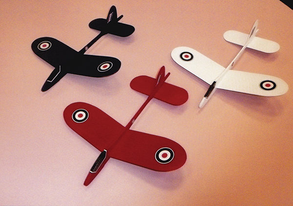
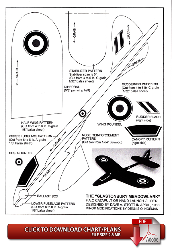
In early June, Mike Nassise sent me a copy of the Tailspin newsletter. Thanks to Mike’s outstanding efforts, Tailspin is always well written and filled with three-views, clear photos, and plans. The July/August 2013 issue featured plans of the Glastonbury Meadowlark Catapult or Hand-Launch Glider designed by FAC cofounder Dave Stott in April 1986. The grace and simplicity of the design captivated me and, with slight modification, I built a couple of them as gifts for my grandsons, Joe, age 11, and Pete, age 9, who were to have accompanied their father (my son, Chris) and me to Geneseo. Everyone chose his own color scheme, but I put them all in English markings because the design seemed to call for it. I have included a photo of these gliders, slightly modified plans, and construction notes.
Fuselage
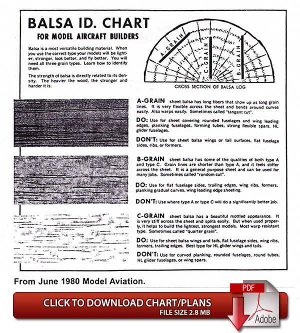
Total length: 111/4 inches I. Made from 6- to 8-pound A-grain balsa sheet in two pieces that are later joined around the wing’s center line.II. 1/64-inch plywood nose reinforcements (make two).
III. Circular ballast box cut into balsa nose (used if additional nose weight is needed).
IIII. One (1) plywood nose reinforcement is permanently glued to the model. The other is temporarily tacked to the other side of the nose during test flights. If nose weight is needed, add modeling clay to the nose. Once the balance is achieved, remove the temporary plywood, place the clay inside the ballast box, and permanently reattach the plywood nose reinforcement.
Wing
Total span: 10 inches I. Make from 4- to 6-pound C-grain 1/8-inch balsa sheet.II. Total dihedral: 11/4 inch (or 5/8 inch per wing half).
III. Carving the airfoil:
- A. Draw carving reference lines at 1/4-inch intervals from the wing center to the wingtip, parallel to the LE.
- B. The high point for the airfoil will be between 3/4 inch and 1 inch behind the LE.
- C. Both LEs will be tapered using a blade and sandpaper block to a uniform thickness of 1/32 inch from center to tip.
- D. The TEs will also be narrowed to 1/32 inch, but will both be carved with washout.
- 1. Right wing half (pilot’s right):
- a. Using a straight edge, draw a line from the bottom of the right TE at the wing center to 1/32 inch below the right wingtip.
- b. Draw a parallel line from 1/32 inch above the center of the right TE to the upper surface of the right wingtip. These lines on the TE will serve as a carving/sanding guide for the TE and will give you a uniform washout for the TE.
- 2. Left wing half (pilot’s left):
- a. Using a straight edge, draw a line from the bottom of the left TE at wing center to 1/16 inch below the left wingtip.
- b. Draw a parallel line from 1/32 inch above the center of the left TE to 1/32 inch below the left wingtip. These lines on the TE of the left wing will serve as a carving/sanding guide for the left TE. Notice that the washout will be less for the left wingtip than the right.
- E. As airfoil carving/sanding progresses from the LE and TE toward the wing’s high point (see Wing, III, B) the carving reference lines will gradually disappear as they are sanded away. The two (2) lines at the highest point will be the last to disappear as the airfoil is completed.
- F. The LEs of both wing halves are rounded. The tip portions of each LE are blended with the contour of the TE portions of each wingtip.
- G. When wing shaping is finished, run some thin instant glue along the LE a short section at a time, wiping it quickly with a paper towel. This will strengthen the wing’s LE and reduce damage to the model as it is trimmed for flight.
- H. The TEs of the wing halves are not tapered thinner than 1/32 inch. Making them too thin increases the likelihood of warping.
Tail Surfaces
I. Rudder/fin:- A. Make from 4- to 6-pound C-grain sheet balsa.
- B. Leave LEs and TEs 1/32-inch thick for structural strength.
- A. Stabilizer span is 5 inches and made from one (1) piece of 4- to 6-pound C-grain balsa sheet.
- B. It is critical to model stability that the stabilizer be warp resistant and absolutely flat. This is particularly important if you elect to paint the model.
- C. Attach the stabilizer so that it has between 0 and 3/32–inch tilt (right tip lower that left tip) when viewed by looking from the back to the front of the model.
Finishing and Painting
I. Min-Wax Spar Urethane varnish found at most hardware stores may be used to seal the raw balsa. Apply it with a small dipstick to the glider and spread it as far as possible. Do one panel at a time. After applying the Min-Wax, gently wipe it off with a paper towel and wait a day before sanding it smooth with 400-grit paper. If the varnish seems to be thick, it can be thinned 10% to 20% with mineral spirits.II. To obtain a color finish, spray paints such as Design Master are effective, but use light coats to avoid creating weight problems.
Supplemental Files and Charts
This Month's Issue

Join the AMA
![]()


3 comments
Template is good
Meadowlark Designer
This is a perfect stuff to be
Add new comment