


eBuster
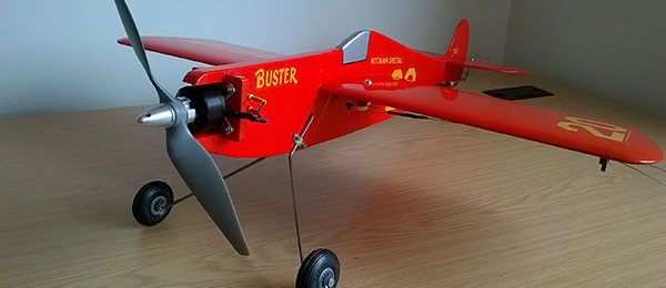
Written by Richard Ryan Converting a Sig Goodyear Racer into a spirited electric CL trainer Construction As seen in the June 2017 issue of Model Aviation.
Bonus video
Specifications
Wingspan: 24 inches Flying weight: 26.5 ounces Power system: RSM Black Tiger BK3530C brushless motor; 30-amp ESC; 2,200 mAh 3S 30C LiPo battery; 9 x 6 pusher propeller; KR Flight ManagerIntroduction
I planned to build a Control Line (CL) trainer for my adult son, Seán. He needed something tough, easy to fly, and sized for ease of transport. He also wanted an airplane with some character and a level of performance to retain his interest beyond the first faltering flights. For low noise and ease of starting, it had to be electric powered. I saw the Whitman Special 20 Buster Goodyear racer in the Smithsonian National Air and Space Museum in Washington, D.C. and thought it would make a good semiscale CL model. Here was my chance to build one, and as a basis, I went for a Sig Manufacturing CL kit. The Sig Buster is intended to be a racer, so it is relatively lightweight. To make it more robust and improve its performance, I made the following changes: • Thickened the wing from 1/4 to 3/8 inch • Thickened the tail surfaces from 1/8 to 3/16 inch • Upgraded to a 3-inch Sig bellcrank with brass-bushed leadout holes • Upgraded the bellcrank mounting • Upgraded the pushrod to a carbon-fiber tube threaded-rod type • Fit an adjustable leadout guide • Upgraded the main undercarriage wire from 3/32 to 1/8 inch, and fit a tail wheel • Fit an adjustable elevator horn to dampen (at least initially) elevator movement • Used pinned hinges for the elevatorElectric Power
I chose Eric Rule’s plug-and-play RSM Distribution 15 electric power system, which includes everything that is needed to get airborne, all ready to install [Figure 14]. I also purchased the brass-bushed 3-inch Sig bellcrank [Figure 08], parts for the carbon-fiber pushrod [Figures 08 and 09], the adjustable leadout guide [Figure 07], the adjustable elevator horn [Figures 10 and 13], the 1/8-inch music wire for the main undercarriage [Figure 12], and Eric’s compatible 15-size laser-cut plywood electric motor mount [Figures 03 and 04], which has an interesting feature. As Eric explained to me (his email support is excellent), unlike for RC, in CL, the motor not only runs at full power for 100% of the flight, but it is also permanently subjected to high centrifugal force in one (outward) direction. To counter that additional strain, Eric provides a capture bearing that is mounted in a bearing box on the back of the firewall, through which passes a rearward extension of the motor shaft [Figure 04]. That external support prevents premature wear on the motor’s internal bearings and increases its life. It is simple and effective, and the bearing box parts are included with the laser-cut firewall.Fuselage
On the kit plans, I redrew the nose to accept the electric firewall, in the process moving the propeller forward 11/4 inch because the electric motor is lighter than a glow engine and I wanted to ensure that the center of gravity (CG) would be well forward for training flights. Without separating the parts, I epoxied the existing laser-cut parts in the kit’s plywood fuselage doubler sheets and transferred the modified front fuselage outline onto them and cut them out. I epoxied the kit’s hardwood engine bearers into the 3/8-inch balsa fuselage core, shortening them so their front faces contacted the rear face of the firewall, leaving sufficient space between the bearers to accommodate the bearing box, rearward motor shaft extension, and the motor leads. For neatness, I planned to pass the motor leads through the fuselage [Figure 04].
Figure 04
After enlarging the curved upper edge of the wing cutout to accept a 3/8-inch-thick wing, leaving the flat lower edge as is, I epoxied the modified plywood doublers to the fuselage sides and filled in the newly created partial voids between the doublers above and below with scrap 3/8-inch balsa [Figure 03].
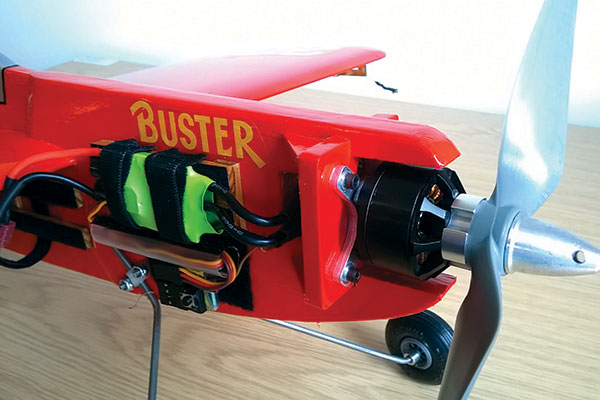
Figure 03
I glued together the laser-cut firewall parts, temporarily bolted on the motor using blind nuts, slid the capture bearing onto the rearward motor shaft extension, and then glued the bearing box parts in place around it, careful not to foul the capture bearing with glue. That way I ensured that the capture bearing was correctly aligned with the motor shaft. I removed the motor and fettled the firewall/bearing box assembly into the fuselage. When a good fit was achieved, I drilled holes through the firewall above and below the bearing box and into the ends of the hardwood bearers behind. I temporarily installed the firewall assembly with wood screws through the firewall and into the bearers and made minor adjustments so that all was properly aligned.
Main Undercarriage
Using the kit’s prebent 3/32-inch music wire CL legs as a pattern, I bent new 1/8-inch wire legs using a Harry Higley Wire Bender. I drilled the main undercarriage retaining hole through the fuselage and installed the new legs with nylon clips, 11/4 x 4-40 bolts, and nylon-insert locknuts [Figure 12].
Figure 12
Had I known then what I know now, at this stage I would have done the following: • Cut a 10mm or 12mm dowel to a length equal to the width of the fuselage, at the position of the undercarriage mounting hole. • Cut a piece of brass tubing with an internal diameter of 1/8 inch to the same length. • Drilled a 5/32-inch hole though the center of the dowel and inserted the brass tube. • Drilled out (in stages) the undercarriage mounting hole in the fuselage to the same diameter as the dowel. • Test-fitted the dowel into the fuselage and the legs into the brass tube within the dowel, then secured the legs with the nylon landing gear clips and 4-40 nuts and bolts [Figure 12]. • When satisfied that all was solid, I would have removed the legs and epoxied the dowel into the fuselage. Installing the undercarriage as shown on the plans resulted in a wobbly gear after the first landing. The dowel method cured the problem. The Sig plans show 11/2-inch wheels, which are slightly small for grass fields, so I used 13/4-inch Du-Bro Treaded Lightweights [Figure 12]. I’d probably now go for 2-inch wheels, but anything larger might start to look like the 1930s. I secured the wheels with wheel collars inside and out and removed the legs and set them aside.
Tail Wheel
The Sig plans show a wire tail skid, but I decided to employ a 1-inch tail wheel. I rebent one of the kit-supplied 3/32-inch main undercarriage legs into the tail wheel wire and wound the end with fine wire to hold the front bend at 180° [Figure 11].
Figure 11
To mount the tail wheel wire, I cut a 1/8 x 21/2 x 3/8-inch plywood mount narrowing back to approximately 1/4 inch to match the rearward-tapering underside of the fuselage. I cut a 21/2 x 1/8-inch recess into the fuselage to accept the plywood mount [Figure 09]. I drilled three holes in the mount—two centrally to take 2-56 bolts (I used 2mm that I had on hand) and one offset to receive a final upward-bend spike in the tail wheel wire [Figure 09]. I test-bolted the tail wheel wire in place and installed and secured blind nuts into the top of the plywood mount with thin CA glue.

Figure 09
I removed the tail wheel wire and epoxied the plywood mount into the fuselage underside recess. When the assembly was dry, I drilled through the mounting holes into the balsa above to accept the full length of the bolts and the wire spike. I then covered the tail wheel mount and punched out the mounting holes. I soldered a small centering washer onto the inside of the wire axle [Figure 11] and permanently bolted the tail wheel wire to the mount. I fitted the 1-inch tail wheel to its axle and retained it with a 3/32-inch wheel collar [Figures 09, 10, and 11].
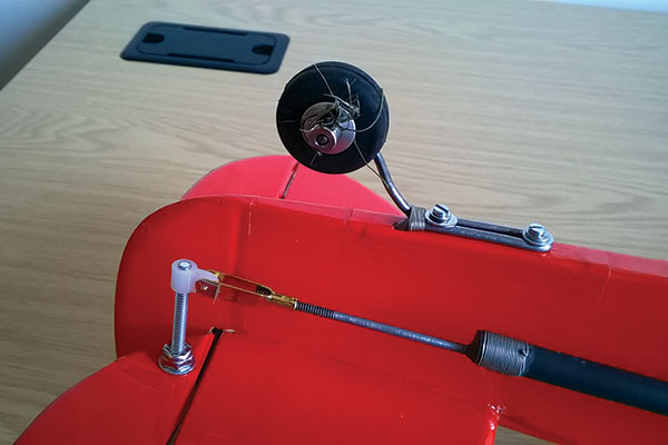
Figure 10
Wing
The kit wing is a 1/4 x 6 x 24-inch flat-bottom airfoil-shaped balsa sheet, plus a 24-inch, 1/8-inch square spruce strip, to reinforce the leading edge (LE). I cut a 1/8 x 36 x 4-inch balsa sheet into 6-inch lengths and using thinned epoxy, attached them cross-grain to the underside of the wing with a layer of ultrafine silk-cotton fabric in between (ultrafine fiberglass would be as good or better). Into the outer 1/8-inch balsa piece, I cut a 1-inch hole close to the wingtip, and fitted into it a 1-ounce lead weight that I covered and secured with a 1-inch-square piece of 1/32-inch plywood. I weighted the wing and left it to dry overnight. The next day, I epoxied a length of 1/8 x 1/4 x 24-inch spruce strip, flat side down, to the LE. When it was dry, I epoxied the kit-supplied 1/8-inch square spruce strip on top of it, backed up to the balsa. The result was a stepped spruce LE [Figure 05].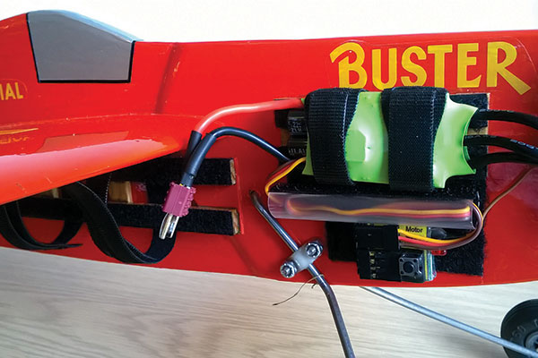
Figure 05
After again drying overnight, I razor-planed and sanded the top of the now 3/8-inch-thick wing to a new airfoil, rounding and fairing the stepped spruce LE into it. The result was a solid balsa wing you could practically chop down a tree with [Figure 16]!
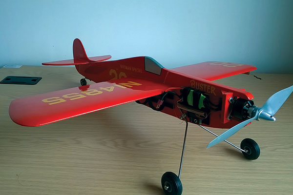
Figure 16
I made up a 3/8 x 1/2 x 4-inch hardwood bellcrank mount and cut a 1/2 x 4-inch hole spanwise in the center of the wing, positioning it so that the hole for the bellcrank would be in the center of the mount. I epoxied the mount into the wing and when it was dry, I drilled out the hole for the 6-32 bellcrank mounting bolt [Figure 08]. Finally, I shaped the wingtips according to the plans [Figure 15].

Figure 14
Stabilizer and Elevators
I’ve always had problems making neat hinge slots in sheet control surfaces. My solution has been to laminate them, and because I wanted to upgrade the eBuster’s tail surfaces to 3/16 inch, this was the way to go. Using the kit-supplied 1/8-inch stabilizer and elevators as patterns, I cut three of each from 1/16-inch balsa sheet, one being cross-grained. In the cross-grained piece of each, which would become the “meat” in the laminated balsa sandwich, I cut recesses for the pinned hinges, as well as slots in the elevator halves for the kit’s 1/16-inch music wire joiner. I then epoxied the parts together and when they were dry, sanded the outer edges round, shaved the elevator LEs to a 90° angle, and set the parts aside [Figure 13].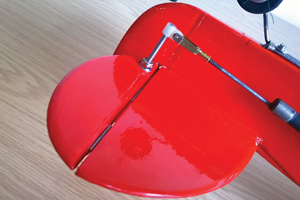
Figure 13
Fin/Rudder
I assembled the kit’s 1/8-inch balsa fin/rudder/dorsal parts and laminated the assembly on either side with 1/32-inch balsa sheet. After sanding the outer edges of the resulting 3/16-inch fin to a rounded shape, I set it aside [Figure 02].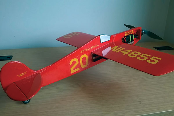
Figure 02
Battery and ESC Placement
To determine where the LiPo battery and ESC would be mounted, I temporarily assembled the model with low-tack masking tape and reinstalled the motor and 9 x 6 propeller. With a simple CG machine—2 x 5/32-inch dowels with pencil eraser tips supported in a block of wood—I determined that, with the ESC on the right fuselage side slightly behind the motor, the battery needed to be mounted flat against the right fuselage side beneath the wing, with the leads immediately beneath the wing’s LE. After covering, I would later epoxy mounting rails for the battery and ESC in those positions. First, I needed to make a plywood baseplate for the battery mount to evenly spread the strain of the battery being pulled outward by centrifugal force during flight. After uninstalling the motor, propeller, and the firewall/bearing box, I cut a piece of 1/32 x 13/8 x 6-inch plywood to fit to the right fuselage side 1/2 inch directly beneath the wing. I then cut that 6-inch piece of plywood into two pieces. The rear piece was attached to the balsa core and the front one was attached to the 1/8-inch plywood fuselage doubler. The cut matched the angle of the rear edge of the doubler. I epoxied those pieces in place on the fuselage side [Figure 05 and 06] then set the fuselage parts aside.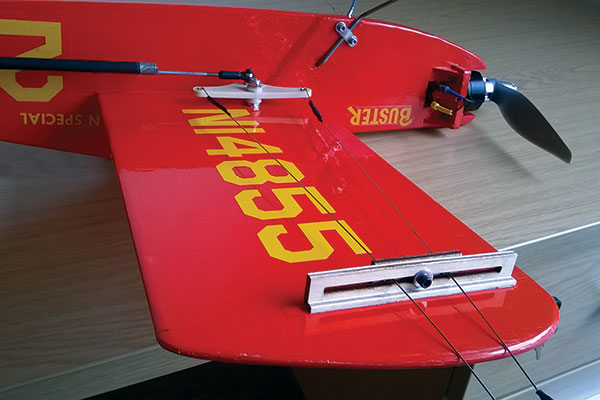
Figure 07
Covering
I separately covered the individual parts—the fuselage, wing, tailplane, both elevators, the fin, firewall/bearing-box assembly, and four firewall mount supports—with bright red Oracover.Final Assembly
I refitted the firewall and bearing box assembly to the fuselage with wood screws and permanently installed it with slow-set epoxy, which is the only type of adhesive that I used throughout. I then epoxied the four covered triangular firewall mount supports (also from the RSM Distribution laser-cut firewall sheet) to the firewall and the fuselage sides [Figure 04]. For a neat installation, I planned to pass the ESC-to-motor leads through the gap behind the firewall/bearing box, but I needed to keep the leads clear of the back end of the motor shaft. To do that, I cut a small plywood partition, covered it, and epoxied it vertically in place approximately 3/32-inch behind the end of the motor shaft, leaving adequate space to the rear of the partition for the leads [Figure 04]. That done, I epoxied the elevator halves together with the kit-supplied joining wire, and when it was dry, I epoxied the elevator to the stabilizer with pinned hinges [Figure 13]. I then epoxied the remaining parts of the model together in the usual way and covered the joints as necessary.Control System
I made up a carbon-fiber tube pushrod from parts supplied by RSM Distribution, followed the included instructions, and linked it at either end to the bellcrank and the elevator. My modifications were a 3-inch Sig brass-bushed bellcrank with the outer pushrod hole cut off [Figure 12] to fit the bellcrank position shown on the plans [Figure 08].
Figure 08
A 4-40 end-threaded rod on the pushrod was screwed at one end into a 4-40 ball link in the bellcrank’s inner pushrod hole [Figure 08]. At the other end, the rod was screwed into a threaded clevis connected to an adjustable elevator horn (a 6-32 bolt) and bolted to the left side of the elevator [Figures 09, 10, and 13]. I epoxied the RSM Distribution adjustable leadout guide to the outer underside of the left wing after removing the covering, and reinforced the installation with a 1/8-inch square plywood strip [Figure 07]. After all of that was done, I made up and installed the CL leadouts.
LiPo and ESC Mounting
Using a #11 blade, I cut the covering around the underlying pieces of low-tack masking tape on the battery-mount baseplate and plywood doubler and peeled them back to expose the bare wood beneath. I then adhered the 3/8 x 1/8 x 13/8-inch spruce strip sleepers onto the 1/32-inch baseplate (for the battery mount) [Figures 05 and 06] and onto the plywood doubler for the ESC [Figures 03, 14, and 15].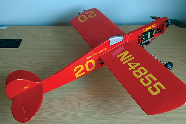
Figure 15
For the battery mount, I used three sleepers. The first went beneath the wing’s trailing edge and the second and third were equally spaced to the plywood doubler [Figure 06]. The front piece of the baseplate that I had epoxied to the angled end of the plywood doubler would be the fourth sleeper [Figure 05]. In that way, the outer surfaces of the three sleepers and the plywood doubler sleeper were all in the same plane, meaning that when I bonded the rails to the sleepers using J-B Weld, the rails were evenly supported along the fuselage side with a consistent 1/8-inch gap behind them, through which Velcro straps would be threaded to retain the battery [Figure 06].

Figure 06
For the ESC, I attached two spruce-strip sleepers to the plywood doubler [Figure 03]. As for the battery mount, I attached spruce-strip rails to them using J-B Weld, again leaving a 1/8-inch gap behind the rails through which to pass Velcro straps [Figure 03]. I sealed all of the spruce-strip parts with yacht varnish to give them a hard, nonabsorbent surface. (Clear dope or another fuel-proofing method would work as well.) Finally, I cut pieces of self-adhesive Velcro to fit the four rails and attached them [Figure 06].
Decals
With the eBuster structurally complete, I applied the kit decals. Unfortunately, the biggest and best markings—the wing registration numbers—were not included. Without them, the model was visually unbalanced, so I decided to make them myself. Another option would be to have them printed.Flying
I no longer fly CL because of a stiff neck, so I asked my Leinster Model Flying Club (LMFC) compadre, Ivan Bolton, to test-fly the eBuster for me, which he did at the LMFC flying field in Phoenix Park in Dublin, Ireland. The eBuster flies like a demon! Fast—4.5-second laps on 52-foot lines, showing its Goodyear genes. Despite that, it’s docile on the handle and easy to fly. It is also safe because it won’t go higher than 30° from the horizontal because of the adjustable elevator horn set to maximum length and the leadouts connected to the outer holes of the 3-inch bellcrank, which, when combined, serve to minimize elevator movement and sensitivity. The elevator horn can be choked up to increase sensitivity and develop more advanced flying skills, as well as thrills! After two terrific flights, Ivan said, “Don’t touch it!” and declared that he was seriously impressed—so much so that he’s now converting a CL Shoestring into a similar electric trainer for a young relative! Seán lives in Cambridge, England. He joined a great local flying club, the Impington Village College Model Airplane Club, where competition CL fliers Steve Mynott and Tony Walsh generously nursed him through his maiden eBuster flights, which were 100% successful. I managed to shoot a video of Seán’s last flight of the day, which is titled, “Do as Your Father Tells You!” If you want to build a CL trainer that has a lot going for it, an eBuster should fit the bill. Between the Sig kit and Eric Rule’s RSM Distribution, you can get most of what you’ll need. (I have no business connection to Eric; I just like his products and his service.) Electric CL is quickly revitalizing this wonderful area of the hobby, so dig out that old handle and build an eBuster. Who knows? Maybe you’ll start a young person on the road to being a CL contest winner! —Richard Ryan [email protected]Sources:
Sig Manufacturing (641) 623-5154 www.sigmfg.com RSM Distribution (951) 678-1406 www.rsmdistribution.comThis Month's Issue

Join the AMA
![]()


1 comments
Wow, I built and flew this
Add new comment