


Hinging for IMAC and 3-D

Written by Jason Noll Any size model will benefit from having a tight hinge line How-to As seen in the July 2007 issue of Model Aviation.
Correctly hinging and gap-sealing your International Miniature Aerobatic Club (IMAC) or 3-D airplane with Robart or hinge point-style hinges can be a frustrating experience. I hope this article makes it easier for you and helps you through that stage of building an airplane or assembling an ARF.

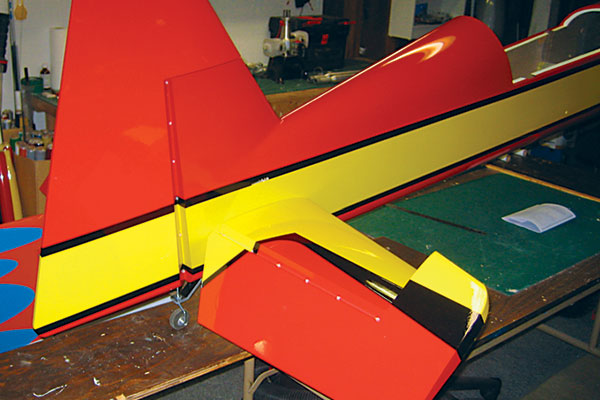
Sealed hinge gaps will make any model, such as this Somenzini Yak, easier to trim and longer lasting.
This method will set you up for a great looking hinge line and will allow you to do a terrific finishing job on the gap-sealing process. There are many ways to achieve these goals, but the one I will share with you works best for me.

Precise hinging not only allows a surface to work better, but it puts less stress on the servo and linkages.
I like to use Robart hinge points because they provide a strong, slop-free joint that I so often see broken on models that were set up with flat-style hinges. The inboard or outboard portion of the surface is where the torsional loads are highest, and I’ve learned that the hinge points hold up better. All that combined with ease of gluing the hinge point-style hinges in place makes this method an excellent way to end up with an excellent-looking aircraft. I recommend that you use the Robart 3/32” Hinge Point (item 305) on 10- to 40-size models, the 1/8” Hinge Point (item 307) on 1.20-size models, and the 3/16” Super Hinge Point (item 309) on 30-40% models.
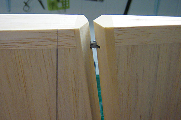
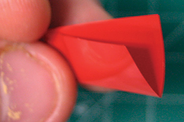
The goal is a tight hinge joint. Double bevels permit deflections of 45° or more.
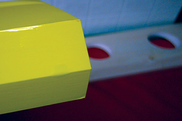
If you are unfamiliar with the gap sealing method and its benefits to you as a pilot, a “gap” in your model’s control surface is the distance between the control surface TE and LE. This gap allows air to travel through while you are flying, creating a high risk of flutter: a violent oscillation of your aircraft’s control surface that can cause it to depart from the airplane.
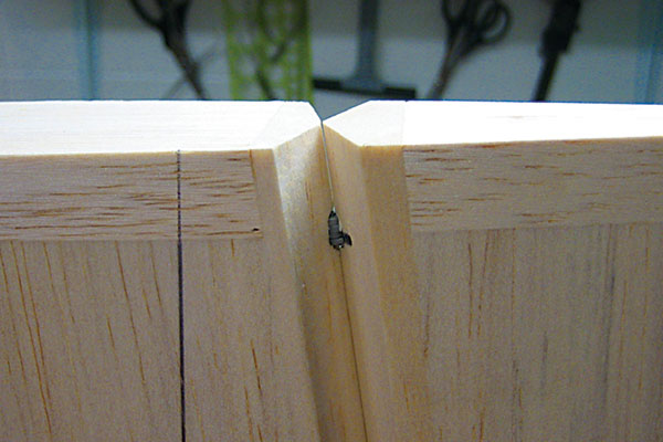
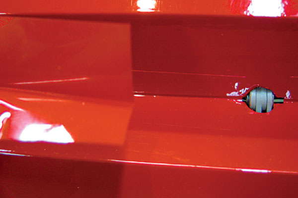
A hinge gap as shown is unacceptable. Diverging air into the gap will promote flutter and surface failure.
Sealing the hinge gap will improve control-surface effectiveness. By not allowing the air to pass through the gap, you are essentially making that air work against your control surface, allowing it to be more responsive and more efficient. The pictures show correct and incorrect gaps. Making It Easy: You will need the following tools to do this job. • Drill • Motor tool • Drill bit (The 11/64 size is right for the 3/16-inch-diameter hinge points used in this demonstration. A slightly larger bit may be required, depending on the wood’s hardness.) • “Pine tree”-shaped sanding bit. • Soldering iron with an old bullet-point tip.
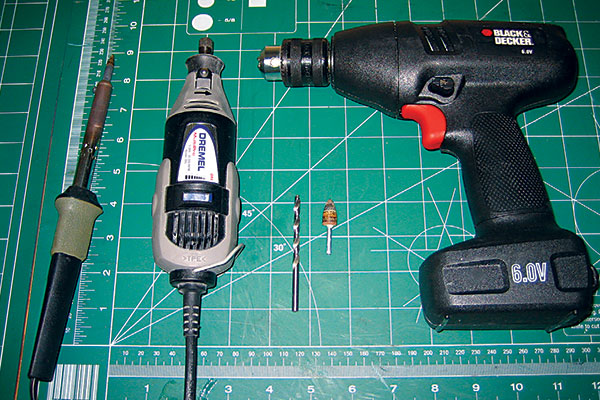
Tools for installing point-style hinges. Use a soldering iron with an expendable tip. An 11/64 drill is used for the 3/16-inch-diameter hinges.
Once you have located all your tools, mark the centerline on the LE of the control surface (aileron, elevator, or rudder) and on the TE of the flying surface (wing, stabilizer, or fin) if it’s not prebeveled. For this article I prebeveled surfaces, and that will act as my centerline. Mark the desired hole locations for the hinge points. As a good rule, on 35% airplanes you should have a hinge every 4 inches on the ailerons and every 3 inches on the rudder and elevators. For 40% airplanes you should have a hinge every 5 inches on the ailerons and every 3 inches on the rudder and elevators. Carefully center-grind each location with the point of the “pine tree”-shaped sanding bit. This will create a small pilot hole you can follow up with an 11/64 drill bit. The pilot hole prevents the drill from wandering or sliding off center; otherwise, that particular hinge may not line up and may even cause binding when the control surface is moved. Drill the center marks to the desired depth. If possible, run the bit all the way in, stopping just shy of the chuck. Now you have the hard part behind you. Relocate your motor-tool bit. Push it in slightly farther to allow for half of the hinge joint to sit just below the surface. This will minimize the possibility of a gap between the surfaces. Be careful to make the depth the same on all points. If you sink the bit too far, it could cause binding and reduce the effective gluing area. It is crucial that the pivot point on all the hinges align. After you have made all the hinge points, cover the model. If you are building an ARF you will start from here. Do not try to cover down into the holes with your iron or attempt to cut out with a knife. Once the model is covered or the ARF is out of the box and you are at the hinging stage, locate the soldering iron with the old bullet-point tip. Go ahead and get it warmed up. Use a pen to mark each of the previously drilled holes hidden below the covering. Carefully sink the soldering iron into the holes. Give it a twist or two and move it around slightly if your iron tip is smaller than the hole diameter. This will create a nicely cleaned and sealed hole.
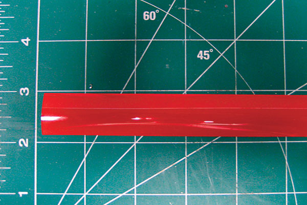
Matching covering is used to seal the hinge gap. A 1-inch-wide strip is typical for a 30%-40% model.
Once all the holes in the surfaces are prepped, glue the hinges in place accordingly. Be sure that the hinge joints are pushed together tightly to eliminate any possible gap. Be sure to monitor them during the drying process. Sometimes they slip a bit; the epoxy heats up and thins as it cures, creating almost a lubricant. Now that you have all the hinges glued in place, you can start the gap sealing process. Measure the distance between each of the hinges. Cut a strip of covering roughly 1 inch wide, depending on the size of the bevel. Cut individual pieces to match the measurements you made previously. Remove the backing from the strips of covering. Fold each piece in half and make a sharp crease. Place the folded piece in the crevice of the bevel and between the hinge points.
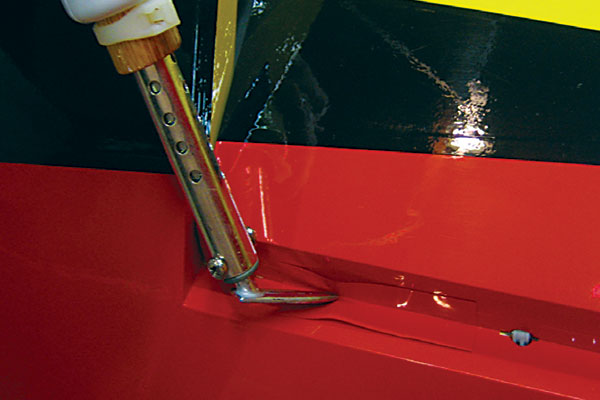
The covering iron’s temperature is lower to prevent damaging the composite fuselage at the rudder hinge line.
Be sure to have the surface fully deflected when ironing the folded piece into place. Control-surface travel will be limited if the surface is not fully deflected, which will lead to the gap seal’s failure because of excessive force applied by the control-surface servo. Continue to fill the spaces between the hinge points and the ends of the hinge line.
Control surfaces deflected at high angles need extra support to handle the abuse of 3-D demands.
You’re finished! Now you have a clean, airtight control surface that will have a positive effect on your flying and last the life of the model.
Step-by-Step with Photos
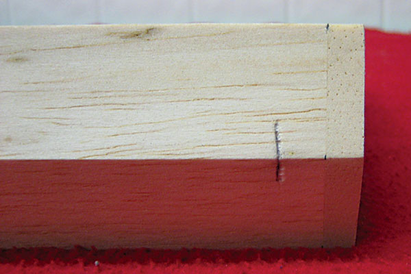
Match the marks on the control surface and the flying surface. The bevel should be on center.
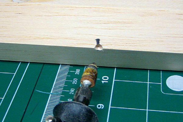
With the motor tool’s speed on low, use the “pine tree”-shaped bit to make a drill center point.
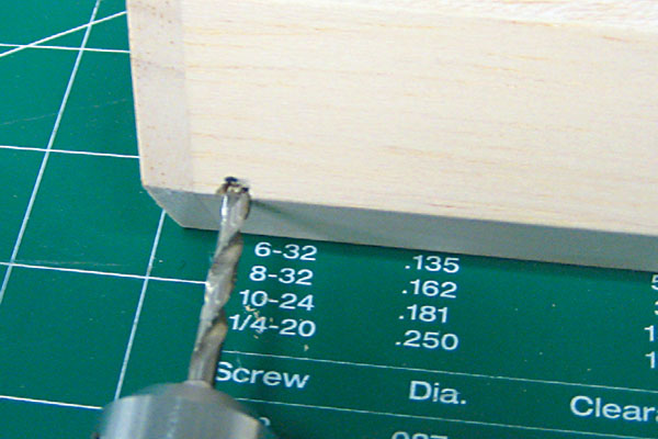
Through the center point, drill an 11/64 hole through the hinge material as straight as possible.
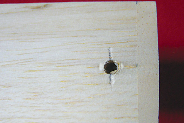
The 11/64 hole is tight for the hinge. It should be deep enough to accept the hinge up the pivot centerline.
Use the “pine tree”-shaped bit to hone out the opening just enough to give the pivot point clearance.
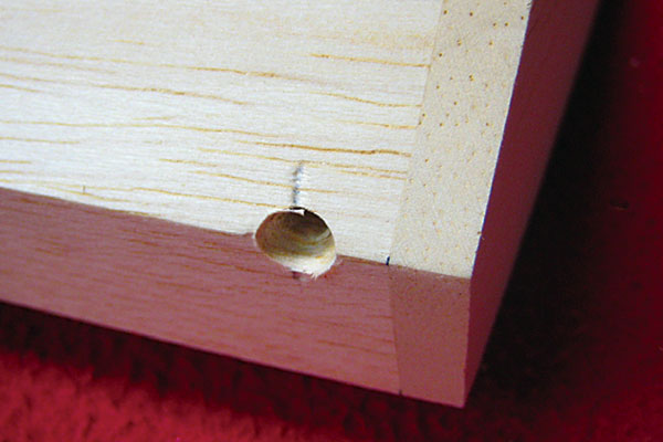
The finished hinge hole should be completed as shown. Do all the hinge points in the same manner.
The center of the hinge pivot point is on the center of the bevel point. Dry-fit the surfaces before covering.
Cover the aircraft, leaving the hinge pockets sealed over until you are ready to install the hinges.
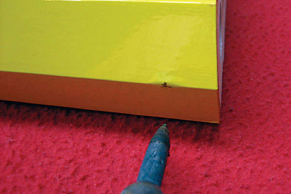
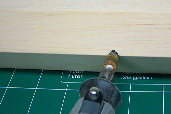
With the hot tip of an old soldering iron, poke through the covering hiding the hinge pocket.
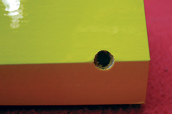
Rotate the iron so it melts the covering. The excess will seal and coat the bare wood.
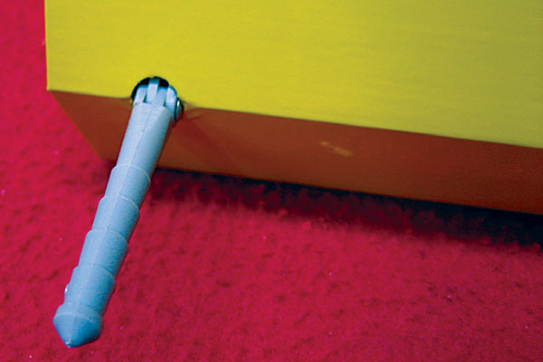
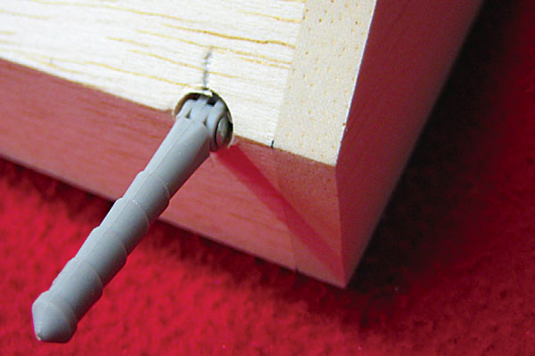
Now is a good time to lubricate the hinge joint. Securely glue hinges and install the control surfaces.
Crisply crease the sealing strip down its length. The adhesive side should be facing outward.
Fully deflect the control surface. Cut the sealing strips into lengths that fit exactly between the hinge points.
With a trim iron on low heat, adhere the covering inside the hinge bevel. Work one side at a time.

You can use scraps of covering to transfer the color scheme through the hinge cutout.
-Jason Noll [email protected]
Sources:
Horizon Hobby 4105 Fieldstone Rd. Champaign, IL 61822 (217) 352-1913 or (800) 338-4639 www.horizonhobby.com Robart Manufacturing Box 1247 Saint Charles, IL 60174 (630) 584-7616 www.robart.comThis Month's Issue

Join the AMA
![]()


2 comments
Good Job! Jason is an
centering hing points
Add new comment