


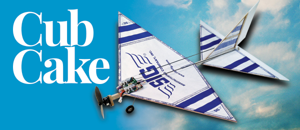
Cub-Cake
Would you like to read more about small-field and indoor models?
Check out free content from AMA's Park Pilot magazine - a quarterly publication that inspires, informs, and instructs small-field and indoor aviators!Written by Tim Bailiff Turn the AMA Cub into an electric RC model Construction article Photos by Maggie Madril As seen in the full March 2016 issue of Model Aviation.
For as far back as I can remember, my brother Dan and I loved building model airplanes. Each new build was an adventure we truly enjoyed. In the day, there was no such thing as an RTF or an ARF. If we wanted an airplane to fly, we had to build it. Our town had a terrific hobby shop that was a wonderland of model airplane kits. My only source of money was the weekly allowance my parents gave me, so the price of the model kit was everything. In 1968, AMA Model Aviation Hall of Fame modeler Frank Ehling designed a simple rubber-powered Free Flight (FF) model that the AMA could use to introduce young newcomers to the hobby. Called the AMA Cub, it had a 121/2-inch wingspan and when the little airplane appeared on our local hobby shop’s shelves, I had to have one. It was inexpensive, simple to build, and capable of some nice flights. My brother and I built a number of these airplanes and had a blast flying them. I’m sure many of you did too. A friend recently gave me a nice selection of model kits including two AMA Cubs! I hadn’t seen one in years and they got me thinking. The result? By combining this classic little FF model with modern micro RC technology, I converted the AMA Cub into a fun, easy-to-fly RC airplane. In fact, it handles so nicely, it’s a piece of cake. So, with that in mind, and with a nod to its original name, I offer you the Cub-Cake. Who would have thought this simple little FF aircraft could become a small park flyer? If this sounds like fun to you, then read on!
A Little History
In the April 1967 issue of American Modeler, a little rubber-powered airplane called the Delta Dart appeared. Designed by AMA’s then-technical director Frank Ehling, the Delta Dart was first introduced at the 1966 Nats. Although some thought the model was too simple and heavy, kids found it easy to build and fly. With pointy wingtips, most of the wing area was closer to the center of the wing, making any warps less problematic. Sig Manufacturing decided to sell the kit renamed the AMA Racer. When the kit appeared, changes had been made that resulted in a slightly more complicated model. This prompted Frank to design another one called the AMA Cub. This airplane has been used in beginner promotions since 1968 and is considered one of the most-produced model airplanes of all time. What makes the Cub such a great beginner’s model? Its one-piece motorstick comes with the correct stabilizer incidence built in. The joints used at the tips of the wing, stabilizer, and vertical fin can be imperfect and still be sufficiently strong because the covering reinforces the joints. Finally, with the exception of the motorstick, the AMA Cub is made entirely of 1/8 x 1/16-inch balsa strips, which make it less likely to warp than other lightweight designs.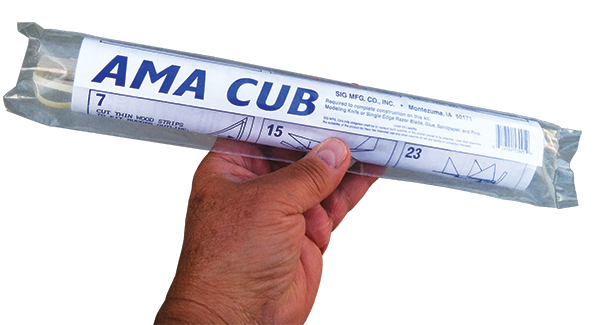
The AMA Cub kit is available through Sig Manufacturing or the AMA retail Web store.
Let’s Build It
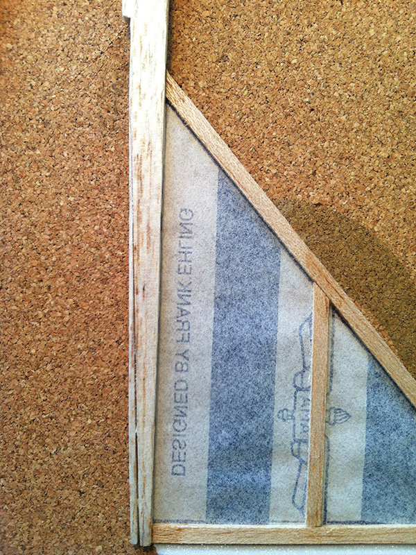
After all these years, I was delighted to see that Sig Manufacturing still sells the AMA Cub kit, as does the AMA online retail Web store. My intention was to keep the Cub-Cake as close to original as possible. To begin, simply build your AMA Cub as described in the instruction sheet that comes with the kit—with a few small changes. Instead of cutting the wingtips and tail feathers off, allow them to continue out to points. You will understand why when the control surfaces are attached. To do this, you will need to lengthen the strip of balsa that forms the stabilizer’s trailing edge (TE) roughly an inch. As you build, remember to glue the balsa strips to the paper covering. Elmer’s Glue works great for this. Take a look at the framing photos and add the four additional supports to the tail surfaces as shown. They run front to back. The stabilizer has three supports and the fin has one. You should have plenty of balsa stock remaining in the kit and this will add greatly to the overall strength of your Cub-Cake. The supports should all be glued to the covering as well.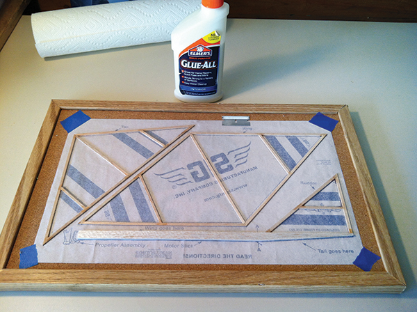
Four additional braces are added to the stabilizer and fin.
Before gluing on the wing and stabilizer, cut a 1/16-inch wedge from the angled underside of the aft fuselage. It should be 4 inches long, measured from the rear of the fuselage, with the widest part of the cut taken from the front. Turn the wedge around and glue it back into place. This will decrease, but not eliminate, the amount of incidence in the stabilizer. Although required for the rubber-powered AMA Cub, the Cub-Cake doesn’t need that much built-in up-elevator. Now finish by attaching the stabilizer with CA glue or epoxy. Add a tiny amount of CA to all of your joints. Don’t use too much because it might run and wick onto your covering.
The stabilizer wedge is turned to reduce incidence.
Don’t glue your wing center joints until the wing is being attached to the fuselage. Use 5-minute epoxy in the joints and along the center bottom of the wing, then measure 1/2 inch back from the front of the fuselage and pin your wing into position. With the airplane sitting upright, set the dihedral by raising each wingtip 21/2 inches. Be sure you have sufficient epoxy in the dihedral joints. Look at the photos to see how I secured the wings as they dried. You won’t be using the propeller assembly or the rubber, but rather than throw them away, set them aside for a future project.
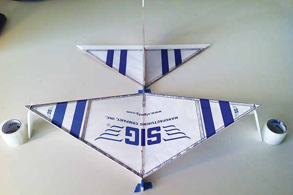
The wing is pinned and the dihedral set while the epoxy dries.
Control Surfaces
Your Cub-Cake uses rudder and elevator for control. You will find the generous dihedral not only keeps the aircraft stable, but also allows the rudder to be effective. Both control surfaces are made from lightweight 2mm Depron foam. The rudder is 1 inch wide. After the proper width is cut, simply hold it against the fin’s TE and cut the top of the rudder as shown in the photo. Its shape is basically an extension of the fin’s leading edge (LE), which is the reason the tail feathers are built into points. The rudder’s bottom should be cut up from the fuselage at roughly a 45° angle. After the 1/2-inch wide elevator is cut to the proper width, hold it against the stabilizer’s TE and cut it following the lines of the stabilizer’s LEs. It will involve two cuts. Finally, bevel each of the control surfaces’ LEs back at a 45° angle. The elevator’s bevel should be on the bottom and the rudder’s bevel on its left. Using 1/4-inch wide strips of Blenderm tape, hinge the rudder on the right side of the fin and the elevator on the top of the stabilizer. Be sure to leave a slight gap so that the rudder and elevator can move freely.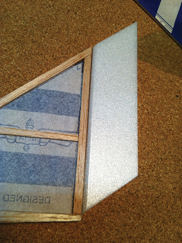
This details the rudder’s beveled LE.
Plywood Pieces
At this point, fabricate the four small 1/32-inch plywood pieces you will need, using the photos as reference. The rudder and elevator horns are cut from 1/2-inch pieces of 1/32 plywood, 1/4 inch wide at the base, tapering to 1/8 inch wide at the tip. Sand the bases so that the horns angle slightly forward. Next, round the tips and then drill a tiny .015-inch hole in the center of the rounded ends. I like to drill a second hole 1/8 inch closer to the base because I like having options. Using the photos as a guide, epoxy the control horns onto the rudder and elevator. The rudder horn goes on the right and the elevator horn on the left. Making a small, shallow slit in the Depron helps ensure a secure attachment.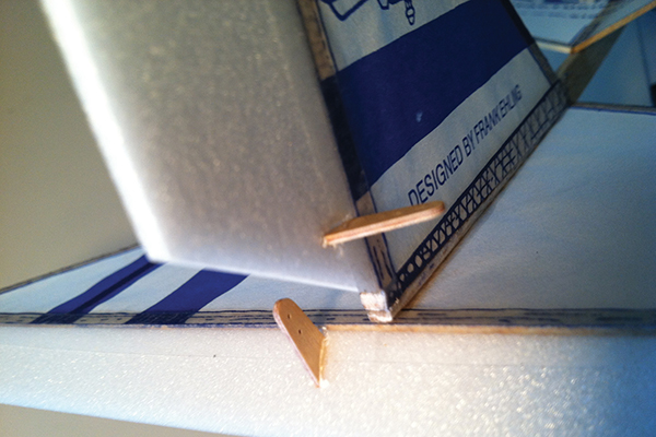
The rudder and elevator horn locations are shown in this photo.
Fashion a plywood mount for the Spektrum AR6400 receiver unit. This great little receiver/servo unit can be purchased at many hobby shops and online. It is the heart and soul of your Cub-Cake. The mount is made from 1/32 plywood, cut 3/16-inch wide and 11/4-inch long. Round the tips and then drill a 1/16-inch hole in each. You want them large enough to fit a #0 x 1/4-inch pan-head screw into each. Use 5-minute epoxy to glue the mount to the bottom of the receiver unit. It should run front to back and be in the middle of the circuit board. Take your time and be sure the mount remains straight and level. Do not use CA glue for this. If it wicks into the servos, the unit will be ruined. The last plywood piece to fashion is the firewall. The HobbyKing AP-03 brushless motor comes with a preattached three-point metal motor mount. Use the mount as a template to shape the triangular firewall slightly larger than the mount itself. When complete, round off the points and use CA to glue the plywood firewall to a 1/8-inch piece of balsa sheet. After the glue has dried, cut and sand the balsa to match the shape of the plywood firewall. Drill three small pilot holes in the firewall to help mount the motor. You will also need to drill a 1/4-inch hole in the center of it as well as clear the propeller shaft and keeper that protrude from the back of the motor. Be sure it is sufficiently deep. Use 5-minute epoxy to mount the firewall to the front of the fuselage. Center it as best you can and add a few degrees of down- and right-thrust.
Airborne Electronics
The AR6400 is installed on top and slightly aft of the wing’s LE. In order to clear the dihedral, you will need to build a small 1/8-inch thick balsa standoff. Make it the same shape as the plywood receiver mount including the two holes, but make them smaller because they are pilot holes. Glue the standoff into position as shown in the photos and then mount your receiver unit using two #0 x 1/4-inch pan-head screws. Carefully connect the motor’s three leads to the tiny HobbyKing 030 ESC. The leads should be pushed through then carefully soldered into the three unmarked contact positions on one edge of the tiny circuit board. As you do this, remember that you might need to swap two of the leads if your motor turns backward. In other words, use the least amount of solder possible. It’s a small space in which to work, but be patient and take your time. On the opposite edge of the circuit board, solder in the three-wire lead with the nano connector, to the three marked contacts. Typically, the white is the signal wire, red is the positive wire, and the black is the negative wire. In the photos, you will notice that I use a three-wire lead with different colors. It doesn’t matter as long as you keep track of where each wire is connected. These same wires must plug into the rear-facing ESC jack, on the back of the AR6400, in the correct positions. When looking into the jack, the black negative port is to the left and the red positive port is in the middle, which leaves the white signal port on the right. As an aid, I marked mine with a touch of fingernail polish. Finally, plug it in. The three-wire lead going to my AR6400 was stripped from a 28-wire ribbon cable I purchased at an electronics store. The three wires lined up perfectly with the AR6400 ESC jack. As an experiment, I removed roughly 1/8 inch of insulation and tinned each wire with solder. I then carefully trimmed and dressed each wire with a fine file until they were smooth and the correct diameter. Then I simply plugged them directly into the jack. It worked perfectly!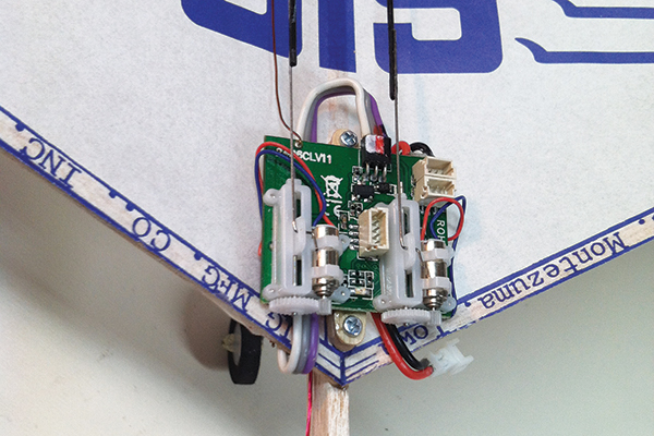
A detailed photo of the AR6400 shows the pushrod and jack connections.
Go ahead and press your GWS EP 3030 propeller onto the motorshaft. If it doesn’t press on easily, hold a small drill bit in your fingers and carefully use it to “file” the hole in the propeller. Be careful not to overdo it. After the propeller has been installed, mount your motor using three #0 x 1/4-inch pan-head screws. For now you can simply let your ESC hang, but be sure everything is positioned clear of the propeller.
Get With the Program
Okay, now it’s time to bind and program your AR6400. This will allow you to center your servos and test your motor. There are a number of transmitters that use DSM2 or DSMX signaling protocol that would work fine for this project. I used my Spektrum DX7 transmitter. To bind, follow the instructions on your specific transmitter. Your AR6400 will automatically go into search mode, indicated by a flashing LED, as soon as you plug in the nano-tech 1S LiPo battery. When the LED stops flashing, the bind has been achieved. Generally, the AR6400 is factory programmed to use its own brushed ESC, so you will likely need to reprogram the ESC jack to allow it to be used with your brushless ESC. This is simple and only takes a few minutes. To reprogram, start with everything unplugged and turned off. Turn on your transmitter and hold full throttle and full left rudder. While holding that stick position, power up the AR6400. The LED on the receiver will go solid and within 5 seconds it will flash three times before returning to solid, indicating the option is changed. This feature “scrolls,” so if desired, it can be changed back and forth by using the same procedure. Now, if you want your rudder to work on your right stick, you must go into your transmitter and mix your rudder 100% with your aileron function. This is necessary because both servos on your AR6400 are hardwired to the elevator and rudder channel. You might need to mix in negative rudder for the servo to move properly. While in your transmitter, go ahead and enter the menu for setting your dual rates as well. Leave your higher setting at 100% and set the lower setting to 60%. After centering the trim settings on your transmitter, check that the linear servos are centered. Next, check that your motor runs properly. If the propeller spins backward, remove the motor from the firewall and swing it and the ESC away from the airplane. Now carefully reverse two of the motor leads on the ESC as described. Again, be patient and take your time. Be assured, your efforts will be rewarded at the flying field.Pushrods
It’s time to make your Cub-Cake’s pushrods! They are both made from sections of .030 carbon-fiber rod with a Z-bend of .015 music wire at both ends. Start by cutting two 9-inch carbon-fiber rods. To one end of each rod, secure a 11/2-inch length of Z-bend .015 music wire. The wire should extend roughly 1/2 inch onto the carbon-fiber rod. Scuffing the wire and carbon-fiber rods ahead of time helps give them “tooth.” When secured with a small amount of medium CA glue, it creates a secure connection. After the glue has dried, connect the pushrods with the Z-bend wire ends to the center hole of both servos. Now make another set of 11/2-inch Z-bend wires and connect them to the elevator and rudder horns. Secure the control surfaces in the neutral position with painter’s tape. Using a small amount of CA glue, connect the free end of the carbon-fiber rod to the wires. This can be tricky, so take your time and make sure they are aligned. After you are satisfied with the connections, finish with a little more CA glue.Landing Gear
My intention was to keep the Cub-Cake as original as possible and use no landing gear, however, seeing how vulnerable the motor and propeller were compelled me to add one. I decided an appropriate compromise would be a single landing strut and wheel, plus a small tail skid. One wheel actually works great because the broad stabilizer keeps the airplane from tipping. The gear strut is made from a 23/4-inch length of .032 wire. Begin at the top by bending 1/4 inch at a 90° angle. Below that, bend 1/2 inch more at roughly a 70° angle facing forward. Finally, bend a 1/4-inch axle 90° sideways at the bottom of the strut. Take a look at the photos for help. Now measure back 21/2 inches from the front of the firewall and carefully push the top of the landing gear into the bottom of the fuselage. Press or carve a shallow 1/2-inch trough into the balsa where the horizontal piece of wire touches. Using medium CA glue, fill the trough, and secure the landing gear in place. Finish by placing a 5/8-inch GWS lightweight foam wheel on the axle. I held the wheel on using a small piece of wire insulation and CA glue.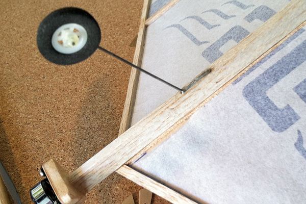
The author added landing gear after seeing how vulnerable the motor and propeller were to possible damage.
For the tail skid, cut a 1/4 x 1/4-inch triangle from a piece of scrap 1/8-inch balsa. Glue it in place using CA. When dry, put a light coat of CA glue on the bottom of the skid to strengthen it. Place two small 1/2-inch pieces of Blenderm tape on the outboard tips of the elevator to protect the foam from scuffing.
Battery Placement
To achieve the proper center of gravity (CG), the 1S LiPo battery must be placed under the left wing on the fuselage. Cut a 1/4-inch hole in the left wing covering slightly behind the AR6400. To ensure that the covering will not rip, reinforce the area with two 3/4-inch square pieces of Blenderm tape, placed on either side of the wing. By cutting through the tape and covering, you will create a hole where the battery lead can pass and not cause any further damage. The battery can then be moved either forward or back and secured in place with a small 1/2 x 2-inch piece of painter’s tape. My battery was placed slightly behind the receiver unit. The proper CG should be at the wingtips.Preflight Checklist
It’s time to make your final preflight check. This is a quick process and will help ensure that you have a safe, successful first flight. With everything plugged in and turned on, check that your controls move in the proper direction. If they don’t, go back into your transmitter and reverse if necessary. The Cub-Cake is unique in that there is no need to worry about control throws. Simply take what you get. I suggest that you switch your dual rates to the lower setting for your first flight and check one final time that your motor runs properly. Make sure that your Cub-Cake balances at its wingtips and reposition your battery as required. One last tip: If you must, always go with your model slightly nose-heavy as opposed to tail-heavy!You Are Cleared for Takeoff
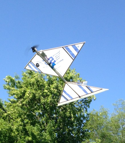
Are you excited? You should be. This is when your work pays off and the real fun begins. Now call the tower and you are ready for takeoff! On the runway, place your Cub-Cake on the ground facing into the wind. Give it full throttle and in only a few feet, you’ll be airborne. You can easily hand launch your airplane, too. When in the air, let your Cub-Cake gradually gain altitude, then reduce the power and trim for level flight. Try different throttle settings until you discover the sweet spot and take a minute to get the feel of your new airplane. The Cub-Cake is easy to fly and still quite maneuverable. When properly trimmed, it will fly hands-free. It’s a great small park flyer. Keep it in close and have fun with its gentle, slow-flying characteristics. That’s what I call relaxing. Will it fly aerobatics? Sure it will! From level flight, with full throttle, it will loop endlessly. It will also roll. That’s right! It does great rudder rolls. Just pull the nose up slightly and give it full rudder. With a little practice and some down-elevator when inverted, you can even pull off a pretty decent roll. How cool is that? Try some stalls as well. The Cub-Cake has no bad habits.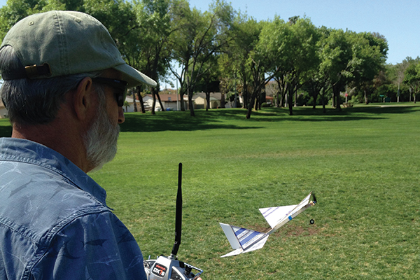
The Cub-Cake has no bad habits and can be flown low and slow and is also capable of loops and rolls.
Bring It Home
When it’s time to land, reduce the throttle and head for home. It’s not a good floater in a dead-stick landing, so plan to save a little battery to carry you in. As you get close to the ground, start the flare and smoothly close the throttle. You will make a beautiful landing.Final Thoughts
Congratulations on a successful first flight and another addition to your squadron. The Cub-Cake is nice to fly, and the more you fly it, the more you will love it. Try it indoors as well. It is great fun in small spaces. Encourage your friends and fellow pilots to build one. Think of the fun you will all have as you revisit your youth together. Time in the air is special and doesn’t last long. Enjoy it! —Tim Bailiff [email protected]Material List
I encourage you to buy what you can from your local hobby shop. If, however, you cannot find something, the Internet is always available. As with many of my construction articles, this one does not include plans, however it does contain construction photos that are designed to aid in successfully completing the project. There are a few small items I’ve not listed, but I will cover them as necessary. I suggest you read this entire article before you begin your build. Also, if you first collect your material, your Cub-Cake will almost “fly” off your work bench! Clever, I know. • 1) AMA Cub kit • 1) Spektrum AR6400 receiver unit or similar • 1) HobbyKing AP-03 7,000 Kv brushless motor • 1) HobbyKing 030 three-amp 1S brushless ESC • 2) Turnigy nano-tech 160 mAh 1S LiPo batteries • 1) GWS EP 3030 propeller • 1) GWS 9/16-inch lightweight foam wheel • 3) #0 x 1/4-inch pan-head screws • 2) #0 x 1/8-inch pan-head screws • 1) Three-conductor male nano-connector with 6-inch wire • 1) 12 x 6-inch sheet of 2mm Depron • 1) 18-inch piece of .030 carbon-fiber rod • 1) 6-inch piece of .032 music wire • 1) 12-inch piece of .015 music wire • 1) 2-inch square piece of 1/32 plywood • 1) 1-inch square piece of 1/8 balsa • 1) Blenderm medical tape • 1) Medium CA glue • 1) 5-minute epoxyBonus photos
Sources:
Sig Manufacturing (800) 247-5008 www.sigmfg.com Spektrum (800) 338-4639 www.spektrumrc.com HobbyKing www.hobbyking.com Turnigy www.turnigy.com GWS (909) 946-7676 www.gws.com AMA retail Web store (800) 435-9262 www.modelaircraft.org/shopamaThis Month's Issue
Join the AMA
![]()


1 comments
AMA Cub rc conversion
Add new comment