
Written by Paul Kohlmann
How to plan out your workflow
Featured in the Construction Series in Model Aviation June 2015.
In previous installments of the “MA Construction Series,” we’ve covered basic toolbox supplies, the vocabulary that modelers use, and a bit about reading plans. I’ve received great suggestions from Model Aviation readers along the way, and one of these ideas resonated with me. Bern Heimos suggested that what many builders need is information about workflow planning.
Workflow planning is simply a way to outline how a project will unfold. When done thoroughly, the planner can identify materials, skills, and equipment needed for the project. Stopping a project in midstream for lack of critical parts can be frustrating. And learning a new skill might be more beneficial if done ahead of a critical need rather than in the heat of the moment.
A schedule and budget can be created through workflow planning. This might sound as though we are turning our hobby into work, but that isn’t the intent. Mapping out the cost in time and money before engaging a project can mean the difference between a project that flies and one that lies shamefully dormant after the interest and investment have run out.
There are a number of ways to approach workflow planning. Here is one simple method broken into three key steps:
Project Goals
Defining the project’s goals answers the “whats, whys, and hows” of the project. What should this model do—fly Aerobatics or compete in Scale events? How big should it be? What flying conditions is it meant for? How many hours and dollars are will be needed? I often bounce back and forth between options during this part of the process, but when my mind is set, it’s easier to see the job through to completion when I feel that I made the right choice.Project Requirements
Thinking the project through brings up the next set of questions. What critical parts and materials are needed? Does your local hobby shop stock the needed items? If not, can it order them or do you need to do so online? Do you have all of the tools that you need? Will you need to learn a new skill? Satisfying these requirements before they are needed keeps the project from stalling.Project Breakdown
This last phase is where the real planning begins. Imagine how the project will proceed from start to finish. Start from a high level and then add detail as you go. Incorporate any instructions that are on the plans. The purpose of the project breakdown is threefold. First, separate the project into manageable pieces. Building a flying model can be a challenge, but building a wing is not. Treating the build as a collection of subprojects makes it much easier to control. Second, keep an eye out for dependencies. Will it be easier to set up the aileron controls before the wings are joined? Putting the subprojects in order prevents rework. Third, the breakdown is useful for time management. When I only have a few minutes to spare on my way out the door to work, I find a five-minute job and knock it out. I focus more heavily on the big things when I have larger windows of time. Now let’s put workflow planning to the test. The project that I am working on is a Miles M.20 of my own design.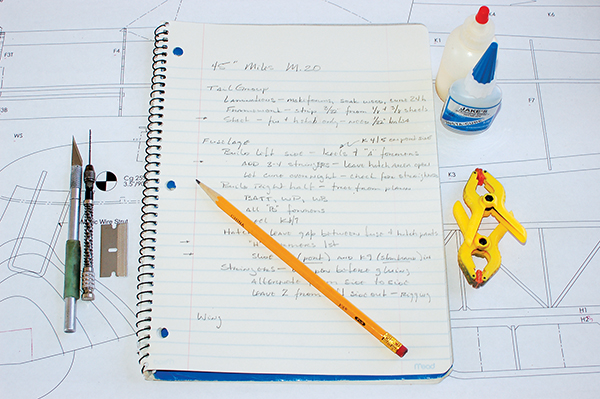
The workflow plan is simply an outline of the steps required to complete the project.
Miles M.20 Project Goals
A wingspan of 45 inches is the maximum that my trunk will hold. Stick-and-tissue construction is my preferred style because of its classic look and light weight. This combination of size and construction ensures that the project’s cost will be modest. Plus, this is a good size for detailing and flying. My plan was to create a new design and scratch-build it. With regard to subject matter, I love warbirds and something sporty and aerobatic was in order. I also love retracts without servos, but sometimes retracts are a hassle. I fly from softball fields a lot and retracts don’t hold up on the dirt. Vetoing the retracts can be a problem, because models with inappropriate fixed gear look goofy to me and making too many belly landings make me a sloppy pilot. So, my project goal was to find a fixed-gear aircraft with the looks of a real fighter and with roughly a 45-inch wingspan. Luckily, there was a photo in my “someday” folder of just such an aircraft. The original Miles M.20 was a British fighter prototype produced while the Battle of Britain raged overhead. The design’s intent was to create a simple aircraft that could shore up Spitfire and Hurricane losses without competing for factory resources. Built almost entirely of wood, with fixed gear and no hydraulic system, the little M.20 went from drawing board to maiden flight in a blistering 65 days (my M.20 has taken significantly longer). Looking slightly like a Tempest with Wellies on, the M.20 performed somewhere between the Spitfire and the Hurricane, but with greater capacity for fuel and armament. Despite the impressive accomplishments of the Miles team, the need for the M.20 passed and the project was scrapped.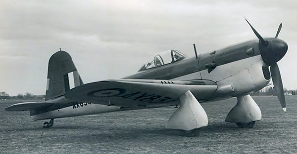
The Miles M.20 oozes with character.
M.20 Project Requirements
Manzano Laser Works cut a short kit for me. There is enough wood in the kit for the stringers and bowed outlines for the tail. The wing’s leading edge requires some 1/4-inch soft balsa and a sheet of 1/32-inch balsa is needed for the tail. A 1-inch and two 3-inch wheels are needed as well as two or three yards of covering. For running gear, I have a 1,000 Kv 480 motor, ESC, and servos recovered from a deceased airframe. That will turn a nice-looking 11-inch, three-blade propeller. One challenge is the distinctively shaped spinner. My Parkzone Bf 109 is close. I’d better order another from my hobby shop. As for skills, I’ll need to laminate outlines, solder, and cover—nothing too exotic on this project.M.20 Project Breakdown
The following partial outline shows my approach to this project. Of course, this is only one of many ways to handle it.I. Prepare
a. Locate motor, ESC, servos, covering, 1/32 balsa b. Pickup hinges, wheels, propeller c. Order spinner, short kitII. Tail
a. Laminate outlines 1. Make up forms • Trace tail outlines on paper • Spray mount to foam board • Cut on scroll saw 2. Soak wood • Cut balsa strips • Fill tub with water/ammonia • Soak 24 hours 3. Laminate and cure b. Build frameworks over plans c. Sheet fin and horizontal stabilizerIII. Fuselage
a. Build left side over plans b. Build right side • Mount battery tray, wing bolt pad, and wing pin pad • Install formers then side keel c. Build hatch • Install formers, leaving a gap between hatch former and fuselage former • Slide hatch rails into place (this order is important!) d. Install stringers (skip a couple on one side until the controls are rigged)IV. Wing V. Control surfaces VI. Electronics VII. Covering VIII. Paint/graphics/detailing
You can see that this is a simple exercise that can be done on a notepad or in Excel. In only a couple of minutes, a few conflicts have been identified. For instance, closing up the fuselage with stringers will complicate installing the controls later. With a little more time, the entire build can be outlined.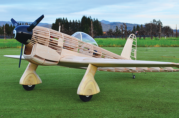
Well-planned projects are less likely to stall.
Conclusion
I often hear stories from other builders about stalled projects. I suspect that workflow planning could have kept many of them moving to the finish line. From here, this series will take a slight turn. During the next four articles, we’ll tackle the construction of the M.20. I’ll focus on particular techniques rather than the normal step-by-step instructions. These techniques will apply to any balsa build.—Paul Kohlmann [email protected] SOURCES: Manzano Laser Works www.manzanolaser.com


Comments
Add new comment