


Build U/Tronics Multichannel Encoder Units

Written by Clancy C. Arnold Multichannel Encoder Unit Part Two Featured in the Model Aviation June 2015
In Part 1, we built a single-channel unit and now we will build the multichannel encoder, which is the handle portion of a multichannel system with the multichannel decoder that goes in the model (see Part 3 of this series). All U/Tronics (U/T) control units are designed for use with standard (not digital) servos or an ESC. The U/T multichannel system can be built as a four-, five-, six-, or seven-channel system. You need to decide how many channels, servos, or ESC you will need to control in the model before finishing the units. The controls may be either variable or switch, controlled by either a simple on/off or a multiposition rotary or a combination of switches. Your choices are only limited by your imagination. I’ll explain the build of a four-channel system. Drawing 2 shows how to add Channels 5, 6, and 7, if desired. The U/T multichannel system is controlled by varying the resistance between the white wire and each channel color wire with zero ohms giving an output pulse width of 1.0 milliseconds every 20 milliseconds, and 10K ohms giving an output pulse width of 2.0 milliseconds every 20 milliseconds. The 20-millisecond time will vary slightly because the individual channel times vary. This will control most standard servos or ESC.
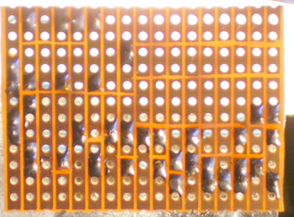
Multichannel encoder circuit board (copper) side, 17 paths with 12 holes each. The paths are cut in 47 places.
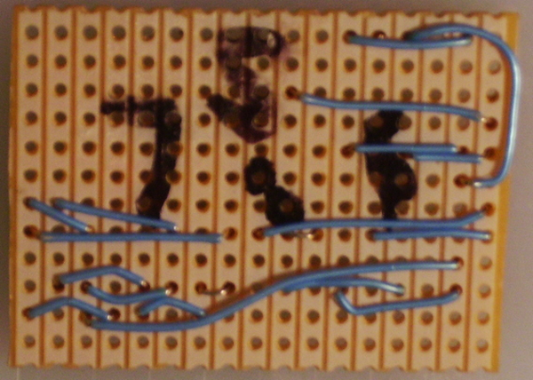
The component side of the multichannel encoder circuit board with jumpers installed.
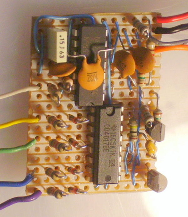
The component side of the multichannel encoder circuit board with its components installed.
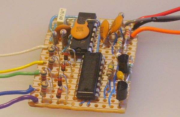
The component side of the multichannel encoder circuit board with its components installed.
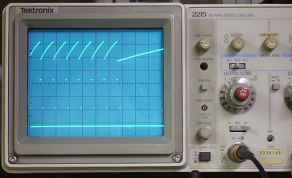
The mulitchannel encoder oscilloscope wave forms, seven channels.
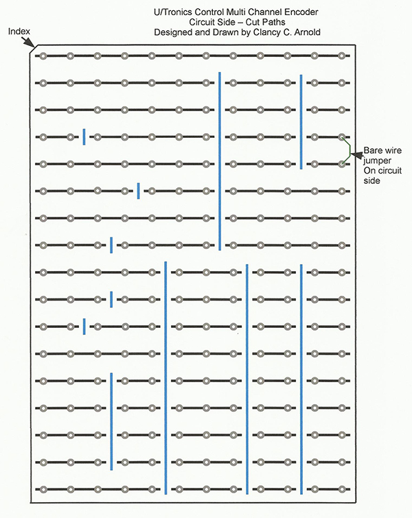
Multichannel encoder circuit side shown.
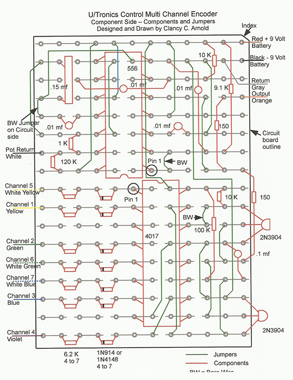
Multichannel encoder component side shown.
Assembly
Saw the board from the prototyping perf board material. Make sure the saw teeth are cutting from the circuit (copper) side. If cutting from the component side, it may pull the copper paths from the board. I cut the boards by sawing through the next set of holes and then filing the edges smooth. You can make two encoder boards at a time from the 35 paths across the prototyping perf board material. Following Drawing 1 and Picture 1, cut the copper paths in 47 places. There is .060 inch of space between holes. Try to remove .015 to .020 inch of copper centered between the holes using a sharp #11 blade and pulling it firmly twice across the path in two places and then use the point to pick the copper between the cuts from the board. Select and bevel one corner as shown in Drawing 1. This will give you an index mark to know which end is up when you turn the board over. Alternatively, you can put paint or tape on the corner to serve as an index marker if you wish. Using a permanent marker, mark on the component side of the board at the location for Pin 1 of the 4017 decade-counter IC and for Pin 1 of the 556 dual-timer IC. Visually inspect the board to verify that the paths are completely cut and a gap exists between the ends of the cut paths. The best way is to hold the board up with the circuit side toward you in front of a strong light source (see Picture 1). Note that all jumpers, components, and wires are inserted from the component side and soldered on the circuit side of the board unless otherwise directed. Always wipe the old solder off of the soldering iron’s tip before soldering each wire or component. I use a damp cellulose sponge. Do not exceed 10 seconds on any one solder joint! Cut to length, form, install, and solder two bare-wire jumpers as in Drawing 2 and Picture 2. After soldering each component or wire, trim the excess flush with the solder on the circuit side of the board as in Picture 1. One end of one jumper passes through the board from the component side to the circuit side and then is passed back through the adjacent hole in the board to the component side. Solder the Bare wire to the two pads. Cut the end of the bare wire flush with the component side of the board. Cut a 2-inch length of insulated solid copper wire, strip one end approximately 3/8 inch, form it into a J, and install it from the circuit side and solder according to Drawings 1 and 2 and Picture 1. Trim the bare end flush with the component side of the board. Form the insulated end of the wire as shown in Drawing 2 and Picture 2, strip away the excess insulation, and insert and solder the jumper. Cut the insulated solid copper wire to length as required for each of the 16 additional jumpers. Strip both ends of each roughly 1/4 inch, form, install, and solder per Drawing 2 and Picture 2. Form the insulated wires around (not across) the bare tinned wires or any other insulated wires. Visually inspect the board for solder bridges between paths as shown in Picture 1. Verify that all jumpers are installed correctly per Drawing 2 and Picture 2. Many of the jumpers are inaccessible after the integrated circuits are installed and soldered. Warning: Before handling any integrated circuit or transistor always touch a grounded piece of metal to reduce the chance of static electricity damaging the IC or transistor. The proper orientation of the IC is determined by the location of the indexing notch in the end of the molded case which is at the Pin 1 end of the package. Insert the 556 dual-timer IC on the component side of the board with Pin 1 in the proper hole. Start one row of pins in their proper holes. Press the other row of pins inward to allow them to enter the correct row of holes using the back side of an X-Acto knife blade. The spring tension in the pins will hold the IC in position for soldering. Visually verify that the pins are in the correct holes! Do not solder at this time! In the same manor, insert the 4017 decade counter IC with pin 1 in the proper hole. Verify that both ICs are down against the board or wires that pass under the ICs. The two IC cases may be touching each other. Solder the pins of both ICs on the circuit side of the board. Solder one row of IC pins at a time and allow time for the IC to cool before soldering the second row of pins. Visually inspect the board for solder bridges between paths (see Picture 1).Soldering
Following Drawing 2 and the pictures, form the leads as required. Insert and solder the component leads in the proper holes. Trim off the excess leads flush to the solder joint. Form the leads of the two 2N3904 transistors as required, install, and solder. Note that one is mounted with the flat side toward the board and the other one is mounted with the flat side away from the board. One at a time, form the leads of a component as required. Insert, solder and trim off the excess leads. Start with the two 10K resistors then add the 100K, 9.1K, and two 150-ohm resistors. Add the four .01 disc capacitors, the 0.1 mF capacitor, and the 0.15 mF capacitor. Add the 1K and 120K resistors. Determine the number of channels you wish to control. Locate by channel number without skipping one, then install and solder the appropriate number of 1N 914 or 1N4148 diodes making sure they are installed with the black band where indicated. Install and solder the appropriate number of 6.2K resistors. Strip off 1/4 inch of insulation and tin both ends of each colored insulated stranded wire. I use the channel colored wires indicated on Drawing 2. You may substitute as required, but be sure to use the same color code on the decoder build and mark the colors you used on your copy of Drawing 2. Insert in appropriate hole and solder each wire. Visually inspect the board for solder bridges between paths. See Picture 1.Test Time!
Using an ohm meter, measure that the resistance between the red and black wires that go to the 9-volt battery is greater than 6K ohms. If not, repeat the stripping and tinning process and verify that all component leads are in the correct holes. Except for checking the operation of the unit with an oscilloscope, you are done until you build the multichannel decoder described Part 3 of this series of articles. If you have access to an Oscilloscope, two-channel minimum preferred. On the encoder, temporarily tack-solder a quantity of 10K resistors equal to the number of channels to the white wire. Tack-solder each one of the channel color wires to the opposite end of each 10K resistor. Connect the encoder to a 9-volt battery. Connect the oscilloscope’s Channel 1 to the white wire and set the scope to sync on this waveform. Connect the oscilloscope’s Channel 2 to the orange output wire. Connect the oscilloscope’s ground to the black wire going to the 9-volt battery. The waveforms should be like those shown in Picture 5 for a seven-channel encoder. If fewer channels are planned, there will be one 2-millisecond ramp for each channel and the number of pulses on the second trace will equal the number of channels plus one. Each space between pulses on the oscilloscope’s Channel 2 should be 2-milliseconds long. Short out the 10K resistor connected to the yellow Channel 1 wire. When that channel 10 K resistor is shortened, it should cause the first space to reduce to 1 millisecond. If that worked, repeat the test for each channel wired. In the final part of the series, we will build the multichannel decoder that will convert the string of pulses on the encoder output to control signals for the servos or ESC that are connected to it in your model.Bill of Materials
All of the parts are available on eBay.- One prototyping perf board, 1.7 x 1.2 inch (17 paths of 12 holes each)
- One 556 dual-timer IC, 14-pin dip package
- One 4017 decade counter IC, 16-pin dip package
- Two 2N3904 transistors
- Four to seven 1N4148 or 1N918 switching diodes (red glass w/black band)
- Four .01 mF disc ceramic capacitor (103Z)
- One 0.1 mF monolithic capacitor (axial leads)
- One .15 mF 5% stable-base Mylar capacitor, 0.2-inch lead spacing (rectangle)
- Two 150-ohm 5% 1/4-watt resistor (brown, green, brown)
- One 1K ohm 5% 1/4-watt resistor (brown, black, red)
- Four to seven 6.2K ohm 5% 1/4-watt resistors (blue, red, red)
- One 9.1K ohm 5% 1/4-watt resistor (white, brown, red)
- Two 10K ohm 5% 1/4-watt resistors (brown, black, orange)
- One 100K ohm 5% 1/4-watt resistor (brown, black, yellow)
- One 120 K ohm 5% 1/4-watt resistor (brown, red, yellow)
- 24 inches of #26-gage solid insulated wire for jumpers
- 6 inches each of #24 or #26-gage insulated stranded wires, 9 to 12 different colors
Read Parts One and Three


This Month's Issue

Join the AMA
![]()


Add new comment