
Written by Laddie Mikulasko Build a 1930's Experimental Aircraft Product Review As seen in the June 2018 issue of Model Aviation.
Order Plans from AMA Plans Service
Image
Image

Specifications
Model type: Semiscale Skill level: Intermediate Construction: Balsa and plywood Wingspan: 60 inches Length: 56 inches Weight: 7 pounds, 4 ounces Power system: Turnigy 3548 1,050 Kv brushless motor; 60-amp ESC; 4S 5,000 mAh battery; 11 x 6 APC propellerImage

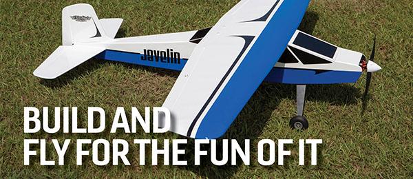
On the ground, the model requires rudder correction. After it is in the air, the aircraft flies well and garners a lot of attention.
The full-scale Mauboussin M.40 Hémiptère was designed and built by a Frenchman, Pierre Maubossin. Its first flight was in 1935, but the project was abandoned in 1937 in order to concentrate on more conventional designs. For most of my modeling life, I have been a big fan of unusual-looking airplanes. In 1989, I came across a drawing with three-views for the unique-looking Hémiptère. Shortly after that, I drew the plans for this model to be powered by a four-stroke glow engine. I built the model and I enjoyed flying it. This time I decided to build a new, electric-powered model. I drew the plans and built it mostly out of 4 mm foam board. However, when I started preparing the article for this magazine, I changed the drawings to use balsa, spruce, and plywood instead of foam. I did this because there are still numerous modelers who are more familiar building models using these materials rather than foam. The model can be powered with an electric 2826/10 300- to 500-watt outrunner or any similar motor.
Building the Wings
Build the front wing in two halves. Use 1/4-inch balsa sheet to cut out the full-depth leading edge (LE) spar, the main spar, and the rear spar. Cut out all of the ribs. The ribs are cut out in three sections: the LE, the middle section, and the rear section. On the first three ribs, cut out 1/2-inch holes for the aileron extension cable. Using 3/32-inch balsa sheets, cut out the bottom LE sheeting and the trailing edge (TE) sheeting. Pin the sheets to the building board directly over the drawing. Glue the bottom capstrips between the LE and TE sheeting then glue the main spars to the bottom LE sheeting followed by the rear spar to the bottom TE sheeting. Glue all of the ribs to the bottom sheeting and spars and glue the LE spar to all of the ribs and to the bottom sheet. Glue the laminated wingtip to the wing. Glue the top balsa LE sheeting to the ribs, to the LE spar, and to the main spar. Glue the top sheeting to the rear spar and ribs then all of the top capstrips to the ribs. Separate the aileron from the wing and glue the aileron LE to it. Glue the hardwood blocks to the rib W1 and to the rear spar to hold the wing to the fuselage. The hardwood blocks are glued to ribs W2 and W3 to hold the main landing gear leg. Glue the 1/8-inch plywood plate that will hold the aileron servo. Build the other half of the wing to the same stage. Pin the 3/32-inch bottom sheeting between the ribs W1. Position both wing halves so that the ribs W1 are sitting on this bottom sheeting. Place the shims under the ribs W7 to achieve the correct dihedral. Now, you can glue the 1/8-inch plywood dihedral joiners to the back of the main spars and to the rear spar. Pull in the extension wire for the aileron servo. Insert and glue the hardwood dowel to the center of the wing. Glue the top sheeting over the ribs W1 and then you can sand the wing.Image

The doubler is glued to the side of the fuselage.
Building the Rear Wing
The rear wing is built in the same way as the front wing. Pull in the extension plugs for the elevator and the rudder servos. Glue the round end plates to the wingtips. You can opt to have this wing be removable or glue it to the fuselage.Building the Fuselage
Image

The fuselage is shown with all of the formers glued to the fuselage sides.
Cut out all of the formers, the fuselage sides, and the plywood doublers. Cut out all of the pieces for the motor firewall box. Glue these pieces to make the box, and then glue the firewall to the box. Depending on the length of the electric motor, the length of the box must be adjusted so that the propeller clears the cowl. At this time, glue this box to the former F4, making sure that it is square with the former. Between the motor box sides and the former F4, glue the 1/2 x 1/2-inch balsa triangular stock. Glue the top and bottom longerons then the plywood doublers to the fuselage sides. Pin one side of the fuselage to the building board and glue the formers F4 to F8 to this side. Make sure that the formers are square with the fuselage side—especially the former F4. Glue the other fuselage side to these formers. Stand the fuselage right side up and glue the top longerons to the formers. Glue the top sheeting to the formers and to the fuselage sides. Glue the bottom sheeting between F8 to F14.
Image

Depending on the length of the electric motor, the length of the box must be adjusted so that the propeller clears the cowl.
After you make the cowl, note that it is held to the fuselage with four magnets. To the former F1, glue a preshaped balsa block. Inside the fuselage, glue two hardwood blocks for the wood screws that will hold the wing and one in the tail to support the tail wheel rod. Sand the fuselage and then cut out the cockpit. Now you can glue the rear wing to the fuselage. Cover the model with your favorite material and install the servos and all of the controls. Check the center of gravity (CG) and if necessary, add lead to the nose to adjust the CG.
Image

This servo controls the tail wheel and rudder.
At this point, the model is ready for its maiden flight. Because the rudders are outside of the propeller blast, the model has a tendency to swing to the left. For this reason, hold the rudders to the right to counter the torque from the propeller. I found that the best way is to apply full power quickly so that the rudders are more effective. In the air, the model behaves like a conventional airplane.
Image

The author’s completed Mauboussin Hémiptère. The full-scale aircraft flew for the first time on April 25, 1935.
—Laddie Mikulasko [email protected] Sources: Turnigy Power Systems www.turnigy.com


Comments
Add new comment