


Great Planes Avistar GP/EP Sport Trainer
Written by Greg Gimlick A Giant Scale Sport ARF Product Review Photos by the author As seen in the March 2016 issue of Model Aviation.
Specifications
• Model type: Giant Scale sport ARF • Skill level: Intermediate builder/intermediate pilot • Wingspan: 90.5 inches • Wing area: 1,448 square inches • Airfoil: Semisymmetrical • Length: 77.25 inches • Weight: 16.5 to 17.5 pounds • Wing loading: 26 to 28 ounces per square feet • Power system: 30 to 35cc gas engine or 63-62-250 kV brushless electric motor; 60-amp ESC; two 4S 14.8-volt 5,000 mAh or two 5S 18.5-volt • 5,000 mAh LiPo batteries • Radio: Four-plus-channel transmitter with receiver and minimum five high-torque servos; 3,200 mAh LiFe receiver battery • Accessories and hardware: Servo extensions and Y connectors according to your setup • Construction: Built-up wood • Covering: MonoKote • Street price: $449.99Test-model Details
• Motor used: RimFire 1.60 (63-62-250) brushless outrunner motor • Propeller: APC 20 x 10E or APC 18 x 8E • Battery: FlightPower FP50 5,000 mAh 5S 18.5-volt LiPos (two in series) • Radio system: Futaba 14SG 14-channel 2.4 GHz FASST transmitter; Futaba R7008SB receiver; seven Futaba S9072SB servos, two Futaba S3001 servos (in floats), Futaba S.Bus Hub 4 Port, Futaba S.Bus SBC-1 Channel Changer; two Futaba S.Bus Servo Hub Cables • Ready-to-fly weight: 16 pounds, 5 ounces (21 pounds on floats) • Flight duration: 8 to 10 minutesPluses
• Built-up construction. • Large, easy battery access. • Great flight characteristics. • Flap option is easy to add. • Tricycle and tail-dragger landing gear options both included. • Excellent covering job. • Easy assembly. • Great power. • Fast to assemble at the field.Minus
• Aileron and flap control horns don’t use backplates.Product Review
When two boxes this big arrive, it’s hard not to be impressed—the UPS delivery person certainly was. When I unpacked the parts, I was even more impressed with the job someone at the warehouse did, packing so much fully covered parts into the boxes and shipping them without damage. Everything was beautifully wrapped and protected. Close inspection of all of the parts found them to be perfect. The option of installing tricycle or conventional tail-dragger landing gear was nice, including wheel pants and gear pieces provided for both. I also got the floats, which were equally impressive and well packed. The thorough instruction manual includes directions on setting up the S.Bus system if you choose. Because I have a Futaba 14SG, this was a no-brainer. The assembly illustrations and description make this a perfect model for someone new to Giant Scale flying. The covering scheme was so nice that I nearly didn’t apply the decals.Assembly
Begin the assembly by thoroughly reading the instruction manual. This will alert you to a couple of areas where you need to decide how you want to do things. Determine now whether you’re going to install the S.Bus system, the type of gear you want to use, and whether you want flaps or not. The manual walks you through these decisions. I labeled each servo for its intended use and programmed them with the S.Bus SBC-1 device. If you’ve never done this, it is clearly explained in the manual. You’ll wonder why all of your airplanes aren’t wired this way once you do it. This is also the time to carefully inspect the covering and seal any loose areas. Surprisingly, I found none, but I did go over the main seams, especially on the floats. Assembly begins with installing the wing servos. The holes are precut and perfectly sized for standard servos. There are strings inside the wing to easily pull your extensions through. If you’re using flaps, you’ll have to cut them loose from the ailerons at this time. I was impressed with the way Great Planes designed that option and it’s one I’ve never seen used before. Each flap is attached to the aileron with two dowels glued through the ends of the control surfaces. If you don’t use flaps, the ailerons consist of the aileron and flap joined together. A simple cut with a razor saw separates them and everything is ready to connect to the servos. My flap and servo wires connected to the S.Bus hub extension so only one wire exits each wing half. It doesn’t matter where you plug them into the fuselage hub because the servos know what they’re for from earlier programming. I wish the control horns on the flaps and ailerons were drilled through and used backplates. Instead, they are partially drilled and secured with #4 x 5/8 screws. Hardening the holes with CA glue keeps them secure, but on a Giant Scale airplane, I prefer backplates for extra security. All of the control rods use threaded clevises on one end and soldered clevises on the other. Silver solder works best and there is a soldering tutorial in the manual. The only problem I ran into was the plating on the inside of the clevis that required some filing before I could get the solder to adhere. Remember, the surfaces have to be extremely clean. The tail surfaces already have the covering removed from the gluing surfaces—what a great surprise that was! I test-fitted the pieces and ensured that they would be square when glued, and then installed the wing for reference. Measure everything carefully and then measure it again to make sure it’s properly positioned before bracing it for the epoxy to dry. Do not try to use 5-minute epoxy. You’ll need more time to get it right. I used 30-minute epoxy, braced everything after it was true, and cleaned up any excess with alcohol before it set. Landing gear is the next step and it requires you to decide which configuration you want. I’m partial to tail-draggers, so I went with that, but pieces for both are included. It’s simply a matter of bolting them in place and connecting the steering mechanisms. Again, each method is carefully explained in the manual. The preinstalled blind nuts on the wheel pants are perfectly aligned with the landing gear legs.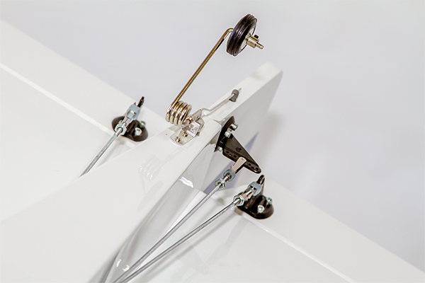
The tail wheel assembly is installed, along with the elevator and rudder horns. The tail wheel assembly fits into predrilled holes with plastic bushings.
Radio installation in the fuselage is next, along with connecting the control rods to the tail surfaces. A battery/receiver tray slides into place behind the servos. Test-fit everything and secure it with epoxy. The tail surface control rods are installed in the same way as were the ailerons and flaps. The guide/support tubes are already glued in place. Align the control horns, drill the surfaces, and secure with bolts in the usual fashion. Everything lined up nicely with the pushrod tubes for free and easy motion.
Motor/Engine Installation
Whether you’re using electric power or a gas engine, the installation method is clearly described in the manual. Each type of power has been carefully planned and the included pieces make for easy installation with particular notes included, depending on your brand of powerplant. Someone put a lot of thought into this. I used a RimFire 1.60 motor, ElectriFly Silver Series 80-amp ESC, and two FlightPower FP50-series 5S 5,000 mAh LiPo batteries. I had previously installed such systems using the Great Planes brushless motor mount for large motors, but because the Avistar included a plywood box assembly, I decided to go with that. It is an ingenious design that, when glued together, won’t come apart. It’s more than strong enough to withstand anything I throw at it. I also like this method because it’s completely modular, so removing it brings the motor, mount, and ESC all off together. Be sure to use threadlocker on the bolts that hold things to the blind nuts. The ESC bolts to the bottom of the mount and gets a nice airflow. The wires to the battery extend back through the firewall to the battery compartment. The batteries are connected in series to provide the 10S power I chose for the Avistar. You can also use an 8S setup and larger propeller. I used the APC 20 x 10E propeller suggested for the 8S setup on my 10S version, and I’m mindful of full throttle times and spikes. Using good throttle management, I can keep within the limits of the motor and ESC according to the data logger I used for the test flights.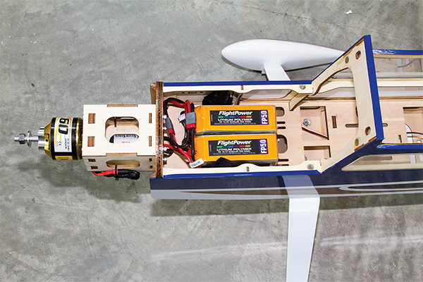
The motor and batteries are installed. The batteries are connected in series to provide 10S power.
The motor/engine installation is completed by attaching the cowl and drilling it for retaining screws after it is properly aligned. Again, if you’ve never had to do this job, the manual walks you through a method that ensures success and can be used on future models.
Control Throws and CG
I used the recommended throws and center of gravity (CG). With my pack approximately an inch back from the firewall, my CG fell close to the recommended 41/2-inch mark. The acceptable range is from 41/2 inches to 57/16 inches back from the leading edge, so there is plenty of room to play with. Mine is currently at the 43/4-inch mark and works well for my flying style. There is a ton of room in the battery compartment to adjust the battery’s position to attain whatever CG you prefer. When I installed the floats, I moved the battery almost to the firewall to get the CG right for float flying. I set the control throws to the high- and low-rate settings in the manual. I’m happy flying on the high rates, but the low rates will nicely tame the Avistar if you’re new to Giant Scale and want to ease into aerobatic flight. I used 25% exponential on all surfaces and eventually increased the rudder throw to the maximum I could get to help the aircraft’s knife-edge capability.Float Installation
This is a beautiful set of floats and again, all of the hard work is done for you. Assembly begins with the water rudders, which is simply a matter of bolting the pieces in place. Each side is the same and each side has its own servo. This eliminates issues found with floats that connect their rudders to the airplane rudder via some sort of flexible pushrod. Even if one side were to fail, the other side still has a servo driving it. Each servo mounts in a preinstalled tray with a hatch cover that is predrilled for its hold-down screws. You have the option of sealing the cover with tape or making a silicone gasket. I chose the gasket method detailed in the instructions. This easy step provides clean installation and ensures that it is watertight. The pushrod to each rudder exits through a tube that is sealed on the inside of the float. I took the extra measure of putting a blob of petroleum jelly in the end of each tube to help prevent water from entering, but I doubt that it’s necessary. The gear legs for the floats and crossmembers are attached to the floats with L brackets and everything is predrilled. Loosely assemble the structure until you bolt it to the fuselage and get everything aligned, then tighten everything down, being sure to use threadlocker on all of the screws. Predrilled, installed blind nuts determine the placement on the fuselage. The front gear uses the same attaching points that the conventional gear used. A dorsal fin replaces the tail wheel assembly and screws into place. The only thing left is to channel the Y connector from the float servos up into the fuselage and attach them to the rudder channel. Be sure to double-check your CG after installing the floats.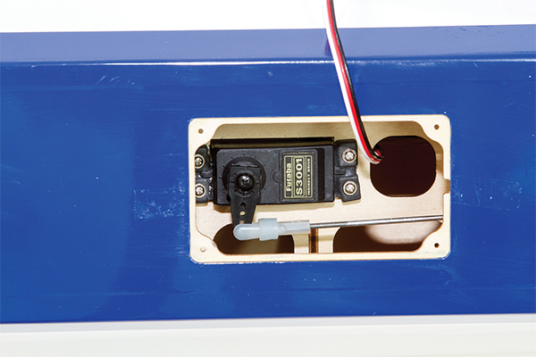
Each float has its own servo and is joined with a Y connector. The completed water rudders are controlled with a pushrod through a tube to the internal servo.
Flying
Anytime I get a chance to fly the first production model in the country, it adds a touch of nerves to the test flight. This needn’t have been the case. The Avistar gracefully began its takeoff run and the tail was off the ground in no time, running on the main gear. It lifted off at half throttle and began its climb with ease. What joy to see this big, beautiful Avistar head up and away without so much as a hint of excitement! A couple of times around the pattern to get a feel for the CG and control authority, and it was evident this was going to be fun. Control throws on high rates were more than adequate, but not enough to startle me. Low rates are docile, but enough to ensure adequate control. I immediately thought this would make a great Giant Scale trainer too. A quick climb to altitude for some stall tests showed that it never really stalls, and it falls off with the CG toward the front of the range. It slowly mushed along, never breaking one way or the other. It did officially stall and drop the nose on later flights with the CG moved aft, but there was never any tendency to snap. Slow-speed flight is a breeze, and flap tests showed it would land at almost a walking speed. Now that I knew it could be a gentle flier, it was time to see if a bit of throttle would liven things up. Full throttle and vertical certainly opened it up to an array of aerobatic maneuvers. Loops, rolls, slow rolls, inverted, Cuban 8s, etc. are all easily done and graceful to perform. If you intend to do aerobatics, moving the CG toward the aft limit will make you happy. The power available for these maneuvers is more than adequate and throttle management will serve you well. The one change I made to help the aerobatics was increasing the rudder throw to the maximum so I could perform better knife-edge maneuvers. Inverted flight takes a slight amount of down-elevator.Float Flying
If you have never done any float flying, you’re in for a real treat. The Avistar would be a great first floatplane because it’s big and stable. The floats are designed and placed so the airplane will handle well in the water with no tendency to plow or sit back on the tail. The water rudders work exceptionally well and keep it controllable, even with a stiff breeze across the lake. I had no problem taxiing against current or waves. Taking off from the water required slightly more power than the land-based flights, but it’s also 4 pounds, 11 ounces heavier. Slow throttle application had it up on the step in no time and its controllability was one of the best I’ve ever had in a seaplane. It lifted off gently and climbed out with ease while it shed water droplets from the floats that glimmered like crystals in the sun. Beautiful! I did the same stall test and other tests with the float configuration and was more than satisfied with the results. Inverted flight took some effort, but it was possible. The big Avistar will do rolls with the floats, but it’s like a big pendulum when they swing back around for upright flight, so be ready. There are no surprises on landing. I did some with and without flaps and I didn’t notice a huge difference. I suspect the floats add enough drag to slow things down anyway. After the approach is set up, you can reduce the throttle and hold everything almost until touchdown. The airplane settled on the back half of the floats and immediately leveled to a perfect taxiing profile. The rescue boat was in the water just in case, but I never needed to use it.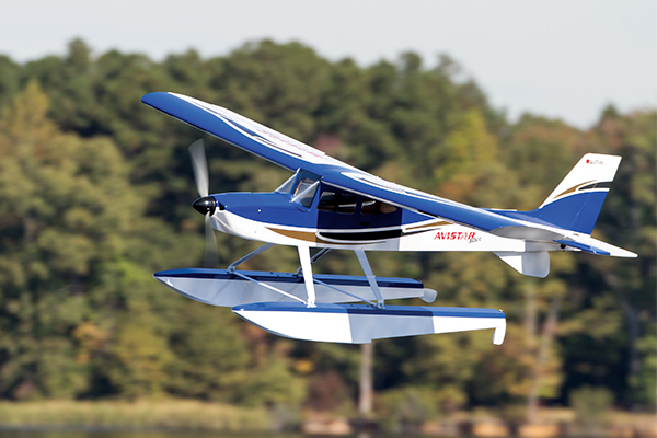
The Great Planes Avistar would be a great first floatplane and the floats are designed and placed so the airplane will handle well in the water with no tendency to plow or sit back on the tail.
Conclusion
I love this airplane! Let me be clear—I really love this airplane! I love Giant Scale, but think many are better off with gas engines. This is not the case with the Great Planes Avistar! This model offers both options, but works exceptionally well as an electric-powered aircraft. The battery pack is reasonably priced and very easy to install. This airplane is one of the easiest Giant Scale airplanes to assemble at the field. I don’t like spending 30 minutes assembling, and this one only takes approximately 7 minutes. The power system is perfectly matched to the airframe and you can set it up for training or go wild with aerobatics. It’s one airplane that covers a broad spectrum of flying styles. Throw the floats on and you’ll instantly love the way it looks. I think it looks even better on floats than on the wheels. It would make a perfect first floatplane. I was surprised that there was enough power to perform aerobatics with the floats installed. The crowd of fishermen that congregated at the lake to watch was testament to how impressive this airplane was. Sometimes I go out to the shop just to stare at it.The Final Word
Great Planes just got it right with this one—it matches the name perfectly! —Greg Gimlick [email protected]Bonus video
Manufacturer/Distributor:
Great Planes (800) 637-7660 www.greatplanes.comSources:
ElectriFly (217) 398-8970 www.electrifly.com Futaba (217) 398-8970 www.futaba-rc.com FlightPower (888) 598-8037 www.flightpowerbatteries.com APC Propellers (530) 661-0399 www.apcprop.comThis Month's Issue

Join the AMA
![]()


Add new comment