


Design Your Own Model with 2D Cad
Written by David Walker As featured on page 33 in the October 2012 issue of Model Aviation. As featured in the Model Aviation tablet app.
Based on feedback from my previous article in the August 2011 issue of MA, the most requested information was where to start. This is often the hardest part of any new project or learning experience.
Because of the somewhat complex nature of computer-aided design (CAD)0, initially this can be a tough question to answer. After some of the basics are explained, it becomes much less complex.
There are basically two types of CAD: 2-D drawing and 3-D modeling. The majority of the feedback I received was regarding 2-D drawing and how to create a set of plans from which to build, so I will focus on that.
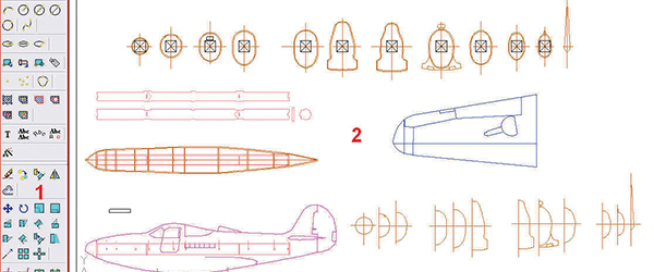
I want to take you through drawing a few simple objects to use in future drawings, and then finally take a three-view, and make a set of plans from which you can build a model. The actual step-by-step demonstration is available on the MA website in video format.
I will introduce methods and tools that work for me, and build upon what I presented in the previous article. The ideas, methods and software presented here and in the videos work for me, but they are by no means the only way of accomplishing the task at hand.
As you become more familiar with CAD, you may find different methods that work better for you. I am using DevCAD for the demonstrations, but the principles are the same for most 2-D CAD programs. I am not promoting this product, or claiming it is the best. I chose DevCAD for the following reasons:
- It is my preferred 2-D drawing software, but is similar to AutoCAD, TurboCAD, and their clones so if you choose to use those programs, you can follow along easily.
- It has a feature that allows you to import a raster image, scale it, and easily trace it.
- It has a nice tile-printing feature.
- The demo is fully functional (except for export and print), so you can try all of the features without having to purchase the program.
- Support after purchase has been quick and helpful.
- If you decide to purchase it, the price is reasonable and you can use the drawings you were working on before purchase.
When you open the CAD program the first time it may seem rather daunting. If you break it down into manageable sections, it becomes much easier.
- Toolbars: You can customize these to your liking. I like to keep the ones I use most so I have more area of the screen available for the drawing.
- Drawing area: This is where you will do the drawing.
- Command line: You do not need to know any commands, but when you click on a tool, the command line will give you hints about what to do next. This is also where you will be typing exact distances and angles.
Some of the basic drawing tools we’ll be starting out with are the line, rectangle, and circle. Along with those are some tools to aid us in drawing such as the zoom and snap tools.
The zoom tools are just what you think they are. They will allow you to zoom in and out within your drawing. Some of the important zoom tools include:
- Zoom Window: You draw a box with the mouse around part of your drawing; the drawing will fill the screen to the area around which you drew the box.
- Zoom+: Zooms into your drawing.
- Zoom-: Zooms out of your drawing.
- Zoom Extends: Fills the drawing area with your entire drawing.
Another important toolbar is the snap toolbar. Snaps are a very useful feature in any CAD program. They allow you to start or stop a drawn object at exact locations. If you decide to have your parts machine cut by a laser or CNC router, it is necessary that there are no broken lines. Even if you are just printing your drawing to build from it, snaps will make your drawing easier to use, and it will look more professional.
There are two snap toolbars. In DevCAD the one at the bottom defines the type of snap; most of the time you set this once and forget about it. Some important ones are:
- Orthogonal: This is seldom used, but is useful when you need to draw only a horizontal or vertical line.
- Polar: This snaps to predefined angles of 0°, 45°, 90°, 135°, 180°, 225°, and 315°. You can also add other angles, or edit the predefined ones if you wish. I rarely turn this one off.
- Object Snap (OSnap): This feature is used in conjunction with the object snap toolbar. This is the one I use the most.
The Object Snap toolbar works when the OSnap feature is enabled. It is best to only have one or two of these active at a time, or the cursor will try to snap to too many places, making it more difficult to get exact placement of where you want to start or stop a drawing object. Some useful snaps to use include End Point, Mid Point, and Circle Center.
When working on your drawing, remember these tips:
- 1) Select a drawing tool.
- Select the snap tool(s) you intend to use (if not already selected).
- Draw the object.
- Enter specifics such as length in the command line. (You can also create a drawing object by connecting two or more points.)
2) Pressing enter on the keyboard will complete a drawing object or command.
3) Pressing esc on the keyboard will cancel whatever you are doing at the time.
4) Save and save often. This is true with any computer program you use.
Before we start drawing our airplane, let’s start with something easier to become familiar with the functionality of a CAD program. For our airplane we will need servos, hardware, and a motor/engine so why not start with those?
In effect we’ll also be building a parts library in the process. You can then use these parts in future drawings. Before you begin, gather the servo you want to draw and a ruler with 1/32-inch markings.
Alternatively, I have an inexpensive caliper that I use for this. The scale is in decimal points, so I don’t need to convert from fractions to decimals.
You can get more precise measurements than that if you wish, but I find 1/32-inch or three decimal places is close enough for my drawings. I like to draw three-views for each component I am going to use in future drawings: top, bottom, and side.
Even if your area of interest is FF, or CL, these are good exercises to learn the basics of CAD. I also find it useful to draw a quick sketch on paper with the dimensions for the parts I will be drawing. This will make drawing the part in CAD much quicker.
Please refer to the video below for detailed, step-by-step demonstrations. The videos cover:
- 1) Creating a new drawing.
- An explanation of units
- Creating a template for future drawings
- Showing/hiding toolbars
- Rectangle tool
- Line tool
- Circle tool
- Temporary lines
- Editing tools
- Introducing polar arrays
- Fillet tool
2) Customizing your drawing environment.
3) Drawing a top view of a servo.
4) Drawing the side, and end view of the servo using the top view as a reference.
5) Drawing servo arms to use with the previously drawn servos.
6) Creating a block library so we can easily use the servo and servo arm drawings in future drawings.
This Month's Issue

Join the AMA
![]()


8 comments
Quality of Video
CAD tool to use...
DraftSight
Cad
CAD video
Video quality and instructors speed.
CAD P-39 Plans where to get them
thanksssss
Add new comment