


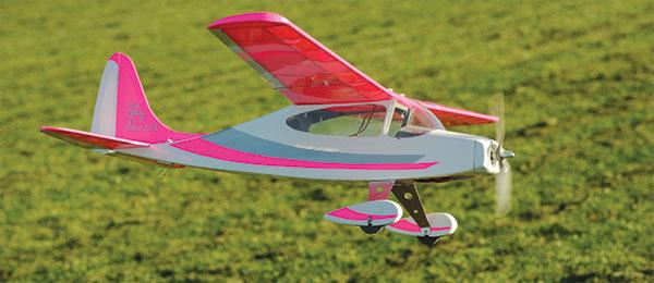
Sky Dancer
Written by Clark Salisbury
Build your own easy-to-fly aircraft Construction feature
As seen in the May 2017 issue of Model Aviation.
Bonus video
Order Plans from AMA Plans Service
|
|
 |

Specifications
Wingspan: 40 inches Length: 31 inches Flying weight: 24 ounces Power: E-flite Park 370 1080 Kv brushless outrunner; 20-amp ESC; 3S 800 mAh LiPo battery; APC 8 x 6 propeller Radio gear: Four-channel radio with four micro servos
Construction feature
Sky Dancer sounds like something that could dance in the sky. My granddaughter, Claire, who will be 6 years old in October, wrote a letter to me asking me to build her an airplane with pink wings, and a radio to go with it. I decided that she needed a four-channel radio to go with a high-wing airplane, with no more than a 40-inch wingspan. I also decided to shoot for 1.5 pounds or less, so that she could carry it. Because she is a dancer, I decided this airplane should “dance in the sky,” or at least do loops and rolls, so it had to have full four-channel control. I decided to build one for myself at the same time. I will save hers for when she is a little older and can handle it well, but meanwhile, the Sky Dancer is lots of fun to fly for somebody who has some experience. Let’s get into the build.
Cutting Out Pieces
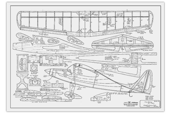
As shown in Figure 01, all of the pieces will be cut from wood sheets as indicated. Stack as necessary for multiple parts, such as wing ribs and fuselage side panels. Carefully glue the sheets together around the edges, so that you can separate the parts later. Glue on all of the paper patterns with a glue stick.
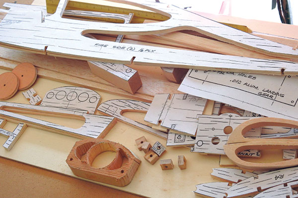
Figure 01
Use a scroll saw to cut out the parts, and note that the nose piece has a 16° cut on the top. Notice also that the fuselage sides have to be spliced unless you can buy a bigger piece of 1/8-inch plywood than I recommended on the Bill of Materials that can be found on the Model Aviation website.
Wheel Pants, Wheels, and Landing Gear
While I was waiting for some wood to arrive, I built the parts you see in Figure 02. When you are building the wheel pants, make sure to build a right side and a left side. The heavier light plywood piece will attach to the aluminum landing gear, so it goes on the inner side.
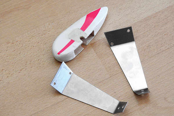
Figure 02
After you have glued the pieces together, carefully sand them to achieve nice rounded corners, and then apply some light spackling to fill in the gaps in the balsa. When they have been lightly sanded, the wheel pants are ready for paint. The aluminum landing gear needs to be cut out, drilled, and then bent in a vice to 45° at two places. Again, make sure you build left and right landing gear. I had a local machine shop shear the aluminum for me, but you could do it with some tin snips. The larger holes shown on the drawing in the aluminum are optional. I was worried about weight, but that turned out to not be an issue. Although not shown in Figure 02 or on the drawing, you will need to build your own wheels. Cut out four pieces of 1/8-inch plywood in 13/4-inch diameter circles. In the center of each circle, drill a 1/8-inch diameter hole. Now, cut out four pieces of 1/8-inch plywood in 1/2-inch diameter circles. In the center of each, drill 1/8-inch holes. These will serve as the wheel hubs. Now, glue two of the 13/4-inch diameter pieces together, and the 1/2-inch diameter pieces to each side. Use a 1/8-inch diameter rod to keep it all centered after you glue the big pieces together. Make sure the plywood grain is perpendicular to the other piece. After the assembly is dry, paint the wheels black.
Tail Feathers
As shown in Figures 03 and 3-b, the tail feathers can be built on a piece of drywall or a building board. Pin the pieces directly to the plans with some waxed paper on top, then glue the elevator together joined by the 3/16-inch wood dowel. Make sure to use a small piece of waxed paper so that you don’t glue the elevator to the horizontal stabilizer.
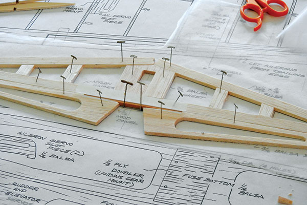
Figure 03
When dry, sand all of the outside edges to a nice radius, slit the rudder and stabilizer, and install/test fit the hinges. Do not glue them in yet. Looking at Figure 3-a, after all of the hinges have been test fitted, drill through the elevator, rudder, and ailerons with a 5/64-inch diameter drill bit, through which a round toothpick will nicely fit.
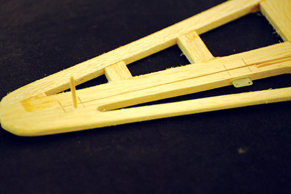
Figure 3-a
Add a little glue into the hole and push the toothpick through. It should stick out approximately 1/8 inch. After it dries, cut it off flush. You will use the toothpick technique to retain the hinges when you are doing the covering. In some cases, the hinge will push through the balsa, and in those situations (center hinges of elevator), simply use a little epoxy on the part of the hinge that has pushed through to retain the hinge.
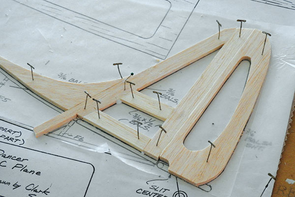
Figure 3-b
Wing
Figure 04, shows starting the wing. First, cut the trailing edge (TE) for the ailerons and a slot for the hinges. Test fit them in place before you pin the TE to your building table. Test fit all of the ribs and put them in place, but don’t glue them yet. R3 should have the aileron servo mount glued to it first.
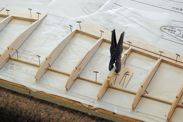
Figure 04
Test fit the servo into the rectangular hole to make sure that it fits. Note that the aileron servo mount is glued to the left side of one R3, but to the right side of the other R3. The 1/8-inch balsa square piece (which is the bottom of the wing spar) should be pinned to the table. Now glue all of the ribs in place, and pin them. In Figure 05, the leading edge has been glued in place. It is made from 1/4-inch diameter poplar dowel. Also, the top 1/8-inch square balsa (top of the spar) has been glued in place. Notice that at the center of the wing, there is a 1/8-inch gap between the square dowels from the left and right wing. This will come together later when dihedral is added to the wing.
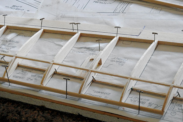
Figure 05
Figure 06 shows the web pieces that form the front of the wing spar when it is glued in place. Cut each one to shape from 1/16-inch balsa sheet. The servo mount slot piece has also been glued in place next to R3. Not shown in the photo, but also glued in place, are the wingtips. I cut them to nearly the right shape, matching the R8 profile before gluing them to it, so that not too much sanding will have to be done later.
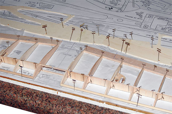
Figure 06
At the top of the photo (Figure 06), I have spliced together the fuselage sides and held them in place with pins. This will save you time later when you start gluing the fuselage together. Figure 07 shows the wing with the center pieces added to hold the dihedral angle. Carefully unpin all of the pins on the outside of both wings, but keep the pins in place on R1. Carefully slide a 1-inch spacer (I use old VHS tapes) to the line on the plans indicated for dihedral. Do this on both sides.
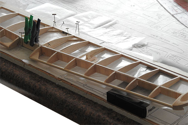
Figure 07
The bottom spar piece will bend slightly, but that is fine. R1 is held stationary on both sides. Now glue in the TE center joiner, the balsa gussets, the web pieces, and the 1/16-inch balsa sheeting to the front and back of the 1/8-inch square spar pieces. The front balsa joiner should not be added until everything else is dry and you have pulled the wing from the plans. When that has dried, do the final sanding where necessary and the wing is nearly complete. The holes in the top of the wing to attach it to the fuselage can be added later. Figure 7-a shows the aileron servo epoxied in place. You will have to do this before covering the wing. Epoxy is the best method to hold the servo because there isn’t space for tiny screws.
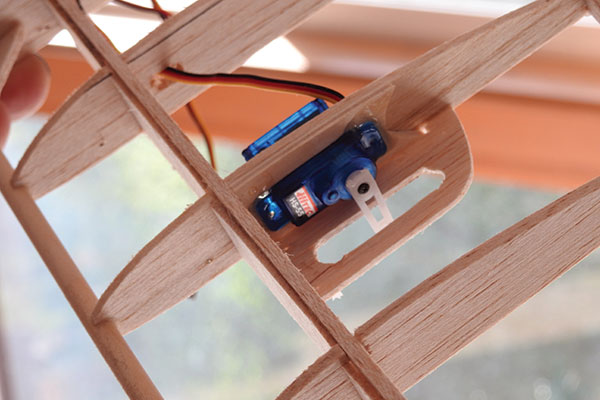
Figure 7-a
The longest servo arm will need to be used with the servo. Just cut off one side of it. Make sure that the servo is centered when you put on the servo arm. You will need to hook up your transmitter, ESC, receiver, and the aileron servo to the receiver and won’t be able to change it later when the wing is covered.
Fuselage
This is a fun, easy-to-build fuselage. Glue the four oak wing mounting pieces to the cabin top plate, and let the assembly dry. As shown in Figure 08, the left side of the fuselage has been pinned to the board. Starting with F1, which is the engine mount, glue it to the side panel.
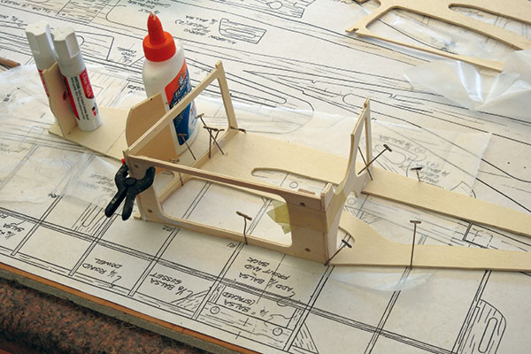
Figure 08
Use something similar to a glue bottle to hold it perpendicular as it dries. Add F3 then the cabin top plate, which will hold F3 perpendicular. Finally, glue in F4 and F2, which is the instrument panel. Also add the 4-inch long, 1/4-inch round dowel to the front of both sides of F3, as shown on the plans. I used tape to hold F3 and F4 to the top plate. When all of these parts have dried, glue the right fuselage side panel in place, holding it with tape. Figure 09 shows the formers at the rear of the fuselage, F5 and F6, that have been added. Put a doubled piece of elastic around F5, and you will find that it holds F6 well.
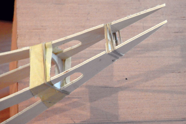
Figure 09
Figure 10 shows the servos attached to the servo mount with screws. That assembly is then glued to the 1/16-inch balsa fuselage top piece, and the fuselage top rear piece is glued to the fuselage side panels. Test fit the servos in place to make sure you are positioning them correctly. If you are going to paint the inside of the cabin, this is the time to do it. I used gray paint to match the striping on the outside of the airplane. When that is dry, glue the landing gear plywood doubler to the fuselage bottom piece, as well as the receiver mount. Trace the location of these parts onto the fuselage bottom piece by temporarily holding it to the bottom of the fuselage.
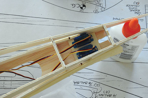
Figure 10
After the fuselage bottom piece has been glued in place, use masking tape and elastics to hold this balsa piece in place. Install the four 4-40 blind nuts into the fuselage bottom for mounting the landing gear before gluing in the bottom fuselage piece. I did not do this, but it will save you time if you do it now. Glue the receiver mount to the back of F3 at the bottom of the fuselage. Figures 12 and 12-a show the front of the fuselage, with three 1/4-inch balsa pieces stacked on top of each other before sanding to match the shape of the instrument panel top. The 1/4-inch balsa should be cut at a 22° angle to mate up with the instrument panel. The scrap balsa shown on the drawing, which is 3/8 x 1/2 x 31/16 inches, has been glued to the front bottom corners of the fuselage side panels.
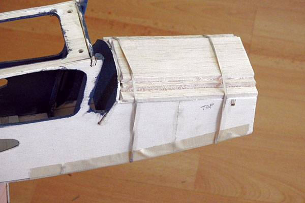
Figure 12
The oak mounting tabs have been glued into the top of the scrap balsa piece, which will end up holding the nose piece in place, using a couple of nylon screws. I had to notch the scrap balsa piece to be able to fit the oak mounting tabs in place to line up with the holes in the nose piece.
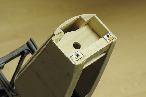
Figure 12-a
Figure 13 shows the battery retainer pieces glued together around the battery. I only glued three pieces together because the front of this will go against F1 later. You might have to adjust the size of these pieces, depending on what three-cell battery you choose to use.
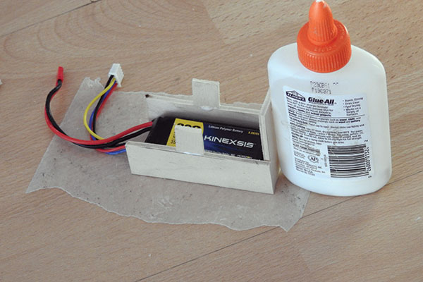
Figure 13
Figure 13-a shows the battery retainer assembly glued in the front of the fuselage. Hold it against F1 while it dries. A 1/4-inch dowel goes through the holes to retain the battery. You can also use a little piece of foam to fill the gap around the battery.
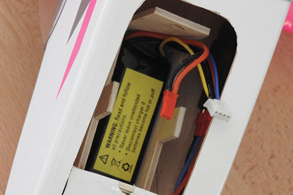
Figure 13-a
In Figure 14, the front cowl has been attached to the oak mounts in the front of the fuselage and the sanding is done. I used two #8-32 x 1 nylon screws, but I ground the head of the screw to a 1/4-inch diameter. I drilled the mounting holes in the cowl to 9/32-inch diameter, but only 1/4-inch deep so that the head of the screw did not protrude. I sanded the front cowl to a nice rounded shape then sanded the entire fuselage to a radius to match the cowl and instrument panel curve.
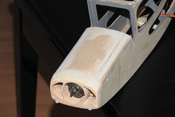
Figure 14
Figure 15 shows the motor mounted with the cowl removed. To fly correctly, the motor needs to have roughly 4° of right thrust. To achieve that, glue the motor mount shim to the left side of the motor mount and let it dry first. You might need to lightly sand the shim piece to get your 4°, then mount the motor to the motor mount using the provided screws.
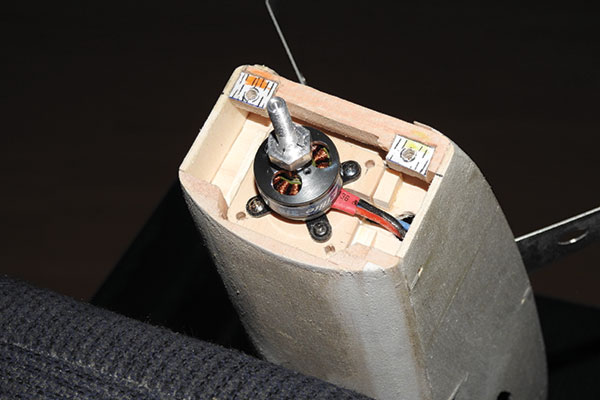
Figure 15
With the cowl in place, center the motor in the cowl opening and glue the mounted motor to F1. If you choose to use a spinner, make sure there is sufficient clearance. Hold the fuselage straight up as you let the glue on the motor assembly dry. I tried using a spinner, but the spinner adapter was not machined quite right, and the propeller vibrated as I revved up the motor, so I ended up just using the propeller adapter that was provided with the E-flite motor. Figure 16 shows the wing in place. If you did not drill the holes already in the front balsa block in the center of the wing and in the rear center of the wing, now is the time to do so. Holding the wing in place, install the nylon screws to test the fit. I measured from the rear of the wing forward, matching the measurements of the oak mounts that were glued in earlier to the cabin top plate.
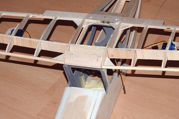
Figure 16
Figure 17 shows one side of the landing gear completed. Screw the stop nut onto a #4-40 screw and through the aluminum support first. As you tighten the nut, make sure that the flats of the hex nut are vertical. This will allow you to keep the wheel pants flat on the bottom. Now, add the other nut and wheel and hold the screw stationary with a screwdriver as you tighten the stop nut. When it is tight, the flats of the hex nut should be vertical. If you decided not to add wheel pants, you are done; if you add the wheel pants, do so now and epoxy them to the aluminum support. Attach them with tiny sheet-metal screws (#2-56 and no longer than 1/4 inch) through the aluminum and into the plywood side of the wheel pant. The wheel pant will slide down and sit on your two stop nuts. You will need to do this before you add the sheet-metal screws. Use the #4-40 blind nuts with the #4-40 machine screws to attach the landing gear to the bottom of the fuselage. It doesn’t hurt to add a dab of epoxy to the blind nuts to keep them from ever coming out.
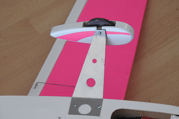
Figure 17
Note that the shape of the aluminum landing gear makes it possible to mount them either way. I chose to mount them in the position that puts the wheels in the most forward position, which is opposite of what my drawing shows. At this point, although not shown in photos, the entire airplane should be covered. The wheel pants and the nose piece need to be painted white. You can use any good glossy paint, and try to match the covering material if you can. The tail pieces should be covered before they are glued to the fuselage, and make sure you leave bare wood exposed where they glue to each other and to the fuselage. If you feel like using the stripes that I have used, the pattern is shown on the drawing. Figure 18 shows the 1/8-inch plywood skid. It is glued to the rear bottom of the fuselage, and holds the vertical stabilizer in place. Also shown is the tail wire skid epoxied into the plywood skid plate. These parts take the place of a tail wheel. The wire should be bent to the pattern shown on the drawing, using 1/16-diameter wire.
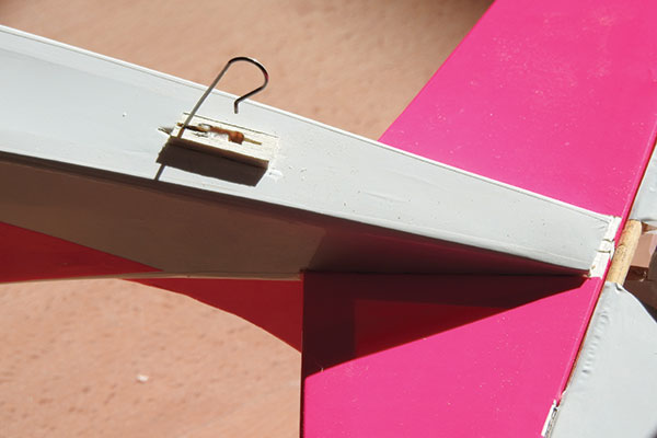
Figure 18
This is the time to hook up the control surfaces to the servos. I used .039 music wire to do this. I had to drill out the servo arms and control horns for the wire. I bent each side of the wire to the right length, and experimented to get the throws right. All of the control surfaces should have approximately 16° of throw—at least that is my preference. You can choose more or less than 16°, but rudder should have no less than that. After hooking up the motor to the ESC, install the propeller and make sure the rotation is correct. If it is not, simply switch any two wires between the motor and ESC, and it will turn correctly.
Flying
I had my friend, Dave Stewart, fly the Sky Dancer for the first time. That flight took place on our club runway, which was much longer than we needed. Because the Sky Dancer is a tail-dragger, it required a lot of rudder correction on takeoff. The takeoff roll was roughly 50 feet with full throttle. After it is airborne, the airplane climbs out nicely. The first flight was to test level flight and gentle turns. Dave mentioned that he was coordinating turns with rudder coupled to the ailerons. With the right radio, that could be done with the radio setup. The second flight was to make sure that the Sky Dancer really could dance—or at least do loops and rolls—and it did so nicely. The loops were large, but Dave’s rolls were much tighter. Structurally, the wing proved adequate for the loops and rolls. If you have a granddaughter, wife, daughter, or a girlfriend, I think the pink wings will be a hit with her. She just might enjoy flying this airplane as much as you do! —Clark Salisbury [email protected]
Sources:
E-flite (800) 338-4639 www.e-fliterc.com Hitec RCD (858) 748-6948 www.hitecrcd.com Model Aviation online www.ModelAviation.com
Membership Benefits Campaign - Building Inspriation
Your membership keeps you inspired!
Your AMA membership keeps you inspired to start that next project with high-quality building features and free plans available for download with many issues of Model Aviation and Park Pilot magazine! AMA members also enjoy discounted pricing for plans and prints purchased through the AMA Plans Service. Discover more benefits in the the AMA Membership Guide atwww.modelaircraft.org/members!
This Month's Issue
Join the AMA
![]()


2 comments
easy to build and fly trainer
Windshield for Sky Dancer
Add new comment