


MA Construction Series - Building the M.20 Tail Group
Written by Paul Kohlmann.
Building the M.20 tail group
Free plans and abridged tutorial
Read the full tutorial in the July 2015 issue of Model Aviation.
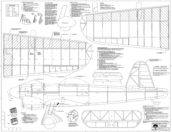
Download Free Plans
Click here for tiled plans (8.5" x 11")
Click here for full plans (44" x 34")

Order Plans from AMA Plans Service
|
|
 |

The M.20 will be the foundation for the next several installments of the “MA Construction Series.” In keeping with the original intent of this series, the subject matter will focus on generally useful techniques rather than step-by-step instructions for this model. For anyone in need of detailed building instructions for the M.20, a build log can be found on RCGroups at www.rcgroups.com/forums/showthread.php?t=2306551.
Tail Group Laminated Outlines
I’d like to say that I jump into new projects head first, but honestly, I usually begin with the tail. The tail group builds quickly, so you can get plenty of satisfaction out of a small time investment. This M.20 design uses laminated outlines for all of the tail parts for strength and light weight. This process began by laying plain paper over the plans and tracing the shape of the tail parts. 3M spray adhesive adhered the paper with the outlines to a sheet of foam poster board. An X-Acto knife or scroll saw can be used to cut along the outlines to create a foam form. A layer of clear tape over the edge of each form prevented glue from sticking to them. Next, 121/16 x 3/16 x 18-inch strips were cut from sheet balsa and soaked overnight in water. That’s enough strips for three plies for each of the three tail parts, plus a few spares. A splash of ammonia helps the wood absorb the water quicker. When the wood has softened, it can be wrapped around the form. Pin one end of the first strip to the foam form, then pull tightly on the free end and wrap the strip around the form. Keeping it tight prevents cracks. Pinning as you go keeps the strip snug against the form. Add glue to one side of the next strip and repeat. Carpenter’s glue works well with the moist wood and it will be easy to sand later. Keep the strip tight and move the pins from the front of the first strip to the front of the second. Add a third strip in the same way and this lamination is done. If the wood won’t cooperate, you have some choices: soak it longer, find more cooperative wood, or use heat. Softer wood is easier to work with. Because you are building a form of plywood, even a lamination of soft wood will be quite strong. Steam can make the strips more pliable. Prebend the strips by holding them over a boiling pot of water and then wrapping them around a suitably sized can. When trained, they should fit the form with ease. When all of the layers are in place, let the laminations completely cure. I find that after a couple of days, they will hold their shape perfectly when removed from the form. If you don’t have that much patience, one builder I know puts his laminations in the microwave! When cured, pin the laminations in place over the plans and fill them in with bracing where shown. 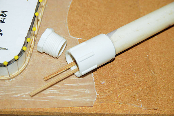
This simple soaking tank was made from PVC sprinkler pipe and fittings.
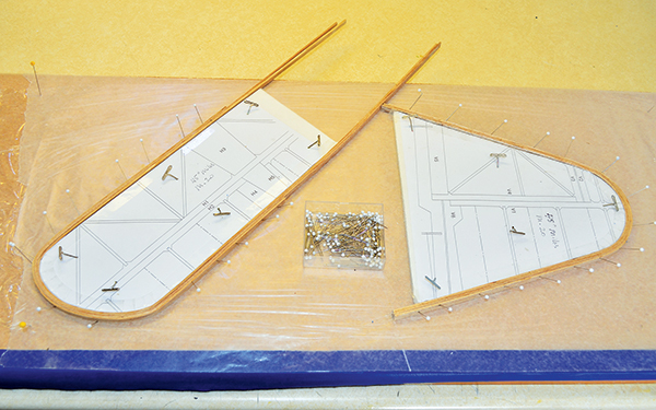
Laminations were created by wrapping three layers of balsa around foam board forms.
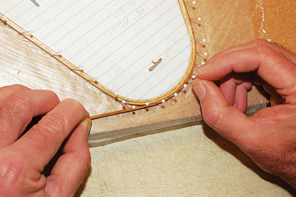
Keep tension on the strip and pull it around the bend, pinning as you go. A layer of plastic wrap under a layer of waxed paper protects the board from diluted glue leaking through the pinholes.
Sheeting
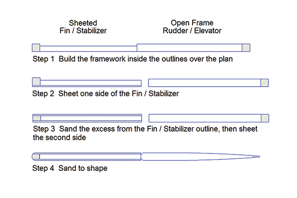
Many full-scale aircraft, including the M.20, have fabric-covered control surfaces. This appearance can be replicated by sheeting the fin and stabilizer and covering the rudder and elevators as open frames. Normally, all of the tail group parts are built up as frameworks of the same thickness. If some of the parts are sheeted, then the others will look too thin. Builders often correct this problem by adding capstrips to the unsheeted surfaces. Capstrips are simply thin strips of balsa used to build up the open frames’ thickness to match the sheeted areas. I find adding capstrips to the framework tedious, so a different technique was used on the M.20. The bracing for the rudder and elevators is made from thicker stock than the bracing for the sheeted parts. This eliminates the need for capstrips. After building the frameworks within the laminated outlines, unpin them and sand their bottom sides smooth. Don’t sand too much—only remove high spots and excess glue with 60-grit sandpaper, then take a quick pass with 200-grit sandpaper. Separate the rudder from the fin and the elevators from the horizontal stabilizer by cutting through the laminated outlines with a razor saw. Trace the fin and stabilizer outlines onto a 1/32-inch balsa sheet. Run the grain parallel to the hinge line for maximum strength. Cut the sheeting to size with a hobby knife. Glue the sheeting so that it completely covers the bottom side of the fin and stabilizer. Carpenter’s glue works well because it allows time to align the sheeting. When cured, flip the parts over and sand the other sides. The rudder and elevators won’t need much, but 1/16 inch will need to come off of the fin and stabilizer outlines. Sand the outlines until they are flush with the framework parts. Sheet the second side of the fin and horizontal stabilizer with 1/32-inch balsa. The tail parts can be installed as flat slabs, but they will look better after some shaping. Radius the leading edges and sand the trailing edges to a taper. The hinge lines will need shaping to achieve rudder and elevator travel without binding.
Hinges
Builders have many choices when it comes to attaching control surfaces. For slow-flying models, simple hinge tape may be enough. Bevel the edges on one side of the hinge line, fit the control surface in place, then apply a strip of tape over the hinge line. Alternatively, a strip of MonoKote or other covering can be ironed on. This type of hinge generally looks better on the top of wings and stabilizers because it does a nice job of covering the gap at the hinge line. CA hinges require more work, but are more durable than tape. These hinges are made of plastic film with an absorbent covering on each side that soaks up CA adhesive. To install them, use an X-Acto knife to cut slits in the balsa along each side of the hinge line. Three or four hinges are usually enough. They can also be cut down if the stock size is too big for your project. Builders have some tricks to help align the slits. I like to align the parts to be hinged, then run a pin through the balsa where the slits will go. The pinhole on each side of the hinge line shows where the slits will be cut. Centering tools and an electric slot cutter are available from Great Planes. Several sizes of small pinned hinges can be purchased from Du-Bro. These are inserted in slits just like CA hinges, but their action is smoother when properly installed. I use epoxy to hold them in place. Applying a dab of Vaseline along the hinge line prevents the epoxy from locking up the action. Flexing the hinge while the epoxy sets is helpful. For extra peace of mind, many builders lock pin and CA hinges into place by staking them with toothpicks. I recently discovered Robart Manufacturing hinge points and found them easy to install—simply drill a hole and pop in the hinge point. These are more durable than they look, plus they can be offset to make really tight hinge lines. They can even be installed at an angle to enable flaps to drop flush with the wing skin. Similar to the pinned hinges, a little epoxy holds them in place, but be careful to keep the movement free. I used hinge points on all of the control surfaces for my M.20 and I’m pleased with them. 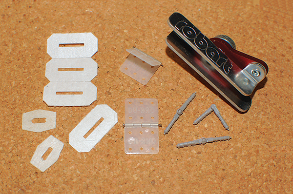
Types of hinges: CA, pinned, and hinge points with drill guide.
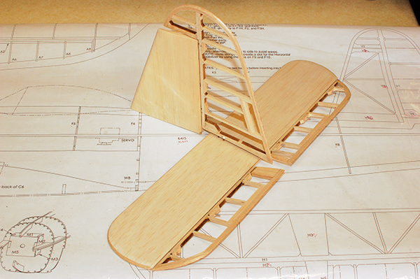
The finished M.20 tail group has been sheeted, shaped, and hinged.
The finished M.20 tail group has been sheeted, shaped, and hinged.
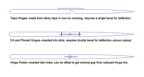
Types of hinges and their installations.
Next Time
Now that the tail parts have been built up, sheeted, shaped, and hinged, we can move on to the fuselage. Next time we’ll frame up the fuselage and install power and servos.
Sources
Du-Bro (800) 848-9411 www.dubro.com Great Planes (800) 637-7660 www.greatplanes.com Robart Manufacturing (630) 584-7616 www.robart.com Manzano Laser Works (505) 286-2640 www.manzanolaser.com M.20 build log www.rcgroups.com/forums/showthread.php?t=2306551
This Month's Issue

Join the AMA
![]()


4 comments
Plans
plans?
Thanks
m20wing webpage?
Add new comment