


Air Ace Models Born Loser P-6E
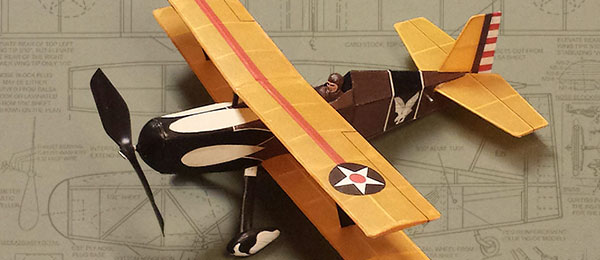
by Dennis Norman Free plans and build article. Care will be given to the steps needed to specifically build the Born Loser P-6E version. Bonus digital feature.
Al Backstrom’s construction article from the October 2000 Flying Models magazine is included as a general guide to building the Born Loser. Because the Born Loser P-6E is a modification of Backstrom’s original, care will be given to the steps needed to specifically build the Born Loser P-6E version.
Building Instructions
A. Preliminary Steps
- Begin by taping the plans to a soft, flat, building board (ceiling tile or something similar).
- Cover the plans with wax paper or some suitable barrier to prevent damage from glue spills, etc.
- Most of the P-6E is built from 1/16-inch square balsa strip or 1/16-inch sheet balsa stock. On the parts sheets, you will note that 1/32-inch sheet, 1/4-inch sheet, and 1/32-inch sheet plywood are also used.
B. Building the Tail Surfaces
- The classic warm-up technique is to build the rudder and elevator, using straight pins to hold the components firmly against the plans. To avoid weakening the structure, place straight pins around (not through) the strip stock.
- When the glue for the rudder and elevator is dry, carefully remove the pins and gently lift the components from the plans. This is most effectively done by sliding a thin piece of metal between the balsa structure and the wax paper-covered plans.
- Once removed from the plans, any excess dried glue should be cut away from the joints. Components can be rounded with sandpaper, but this step is optional for a model of this size and fragility.
- Having built the rudder and elevator, set both aside until ready to cover.
C. Building the Wings
- Like the tail surfaces, the wing is mostly built using a combination of 1/16-inch square and 1/16-inch sheet balsa.
- Carefully cut the wingtips, ribs, and gussets from 1/16-inch sheet balsa (see parts sheet).
- Pin hard 3/32-inch square balsa strips against the plans for the wing’s leading edges LEs). The trailing edges (TEs) are made from 1/16- x 1/8-inch balsa strips.
- Elevate each half of the top wing by placing a piece of 3/32-inch scrap under the tips of the TEs on either side. This will create a stabilizing warp called washout in both sides of the upper wing. When building the bottom left half of the wing (pilot’s left), elevate the tip of the TE 1/16 inch using a piece of 1/16-inch scrap.
- The right half of the bottom wing is built the same as the top wing by using a piece of 3/32-inch scrap under the tip of the right TE.
- The steps mentioned in C4 and C5 create a warp in the bottom wing, which will help stabilize the wing in flight. The lesser washout used on the left half of the bottom wing will counteract the torque or twisting force exerted by the propeller as the rubber motor unwinds.
- Note that the lower wing features two ribs that align with the bottom of the fuselage and help attach the bottom wing. To help anchor the covering, place a piece of 1/32- x 1/4-inch piece of sheet balsa on the side of each rib facing the wingtip.
- Unlike the bottom wing, the top wing center uses two ribs that are placed 1/16 inch apart to form a slot for the model’s pylon. Help anchor the covering by placing a piece of 1/32- x 1/4-inch sheet balsa on the side of each rib facing the wingtip.
- The pylon enhances the design’s stability. Make the pylon from 1/16-inch balsa sheet as shown on the plans; however, the prototype BL P-6E uses an “open” pylon in which two pieces of clear acetate are employed to create the illusion that the upper wing is held on by conventional struts.
- Note that both wings employ 1/16-inch square balsa strips as spars. These are on the top of each wing only. For structural strength, 45°sheet gussets (WG) are added to both wings. Interplane strut receptacles are made from 1/16-inch sheet.
- After each wing is dried, it should be removed from the building board. Sand the LEs and TEs to an airfoil shape, and then set aside to await covering and assembly to the fuselage.
- When the wing halves are fully constructed, raise the tip of half of each wing 3/4 inch to create dihedral. Be sure to preserve the washout in the elevated wing half by placing a support beneath the tip of the wing’s TE.
D. Building the Fuselage
- Cut the main fuselage parts from 1/16-inch sheet balsa. Use 1/32-inch sheet for the sides of the top of the fuselage ahead of the pilot’s headrest, the landing gear struts, and the fuel tank.
- Begin by pinning the 1/16-inch square top of the fuselage side (top longeron) firmly against the wax paper-covered plans.
- To ensure strong joints, place pins directly above of the top of each longeron at the locations where it will come in contact with each vertical upright.
- Cut lengths of 1/16-inch strip balsa to the exact length of each vertical upright.
- Make certain that each vertical upright, when in place, will firmly contact the upper and lower longerons. After cutting the vertical uprights, set them aside.
- Pin an oversize length of 1/16-inch square balsa strip against the plans at the position shown for the fuselage’s bottom longeron. Next, place each vertical strip at its location on the plans. Again, the fit should be snug.
- Apply glue to the top and bottom of each vertical upright and then set it carefully in place between the top and bottom longerons. Add sheet parts as shown on the plans to the nose, wing root, and rear motor peg area (slightly ahead of the stabilizer slot).
- To ensure good contact with the top and bottom longerons, place a pin firmly against the outside of the bottom longeron at the strip’s location.
- Repeat steps D2 through D8 to build the second side of the fuselage. Using the same pinhole locations from the first side should make the second side identical. Each side of the fuselage should align with the other side.
- The inside of each part of the rear motor peg area should be reinforced with 1/32-inch plywood, which should be drilled out before placing it inside the fuselage. Make the hole slightly smaller than the diameter of the rear motor peg. The rear motor peg itself can later be snugly fitted with the use of at small rattail file.
- At this point, the fuselage sides are ready to be joined. Begin by carefully aligning and gluing the tail ends of each fuselage side together at the rearmost vertical spacer of each side.
- Join the front ends of each fuselage side to a temporary rectangular balsa sheet spacer cut to the inside dimensions of the nose. This will be removed after the fuselage sides are permanently joined by the 1/16-inch square spacers.
- Looking at the top view of the fuselage shown on the plans, next cut pieces of 1/16-inch square balsa to the exact lengths shown between the fuselage sides. One pair of pieces at each location should be cut to keep the sides parallel and the fuselage cross section rectangular.
- Add triangular fuselage top pieces 1 through 6 as shown on the plans. In building the prototype, parts 5 and 6 had to be redrawn as shown on the BL P-6E plans because they did not create a rigid enough structure to permit smooth covering of the top rear of the fuselage.
- Following the original design, the top of the forward fuselage is made from pieces of 1/32-inch balsa sheet that join to form a triangular cross section. To make the cockpit more closely resemble a P6-E, the 1/32-inch sheet portions were extended and redesigned as shown on the plans and parts sheet.
- Al’s Born Loser shows a balsa nose block with an optional spinner. Because this would be incorrect for a P-6E, the nose block has been reshaped to give it a more realistic look. The BL P-6E also employs a detachable nose block, which is mounted against a 1/32-inch plywood former with a 1/2-inch square hole cut in it to accommodate the nose block plug. The nose block may be carved either from a block of balsa or laminated from pieces of 1/16-inch balsa sheet as shown on the plans.
- The landing gear is formed from .025-inch music wire. To better meet the BL P-6E’s unique wheel pant-and-strut combination, the landing gear wire was cut to eliminate that portion attaching to the wheels. Instead, the wheels are inserted and held in place in the pants with a portion of a straight pin cut to length for that purpose.
- The landing gear struts are made by gluing two pieces of 1/32-inch sheet to the landing gear wire. To facilitate strut flexion, do not glue the struts to the lower longeron. When the landing gear struts are in place, the wheel pants are carefully glued to the bottom of the struts. Use care to evenly align the wheel pants with each other.
- The 0.16-inch music wire tail skid shown for the Born Loser has been replaced by a tail wheel fashioned from sheet balsa to more closely approximate the look of a P-6E.
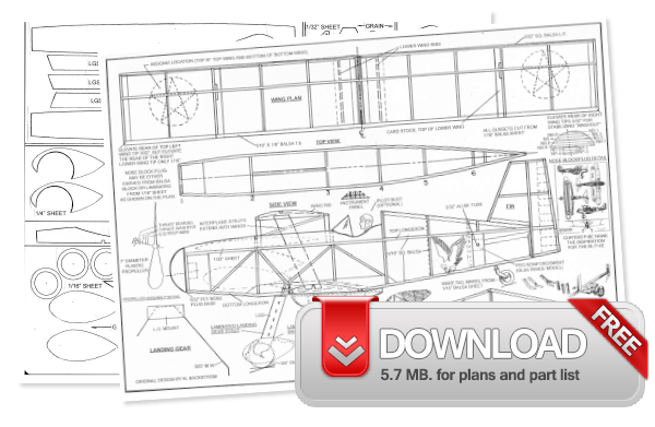
Download free plans by clicking here.
Have fun and happy landings! —Dennis Norman [email protected] FREE PLANS
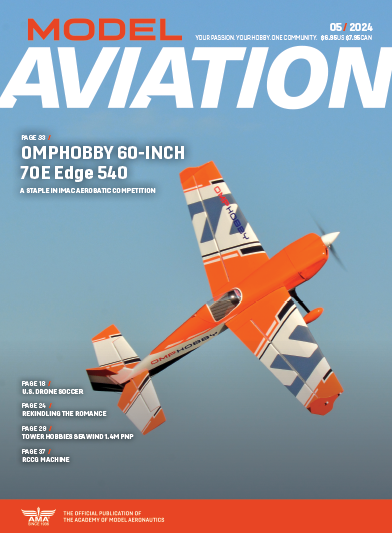
This Month's Issue
Join the AMA
![]()


10 comments
free plan
It may fun to look into these
Great small field model.
great
Any chance anyone has a few
Building Directions
Printer Button
Born Loser P-6E covering
The plans download link is broken..
Re: The plans download link is broken..
Add new comment