


BMJR Models Super Sniffer

Written by Dan Gaston This FF model makes an enjoyable RC aircraft Product review As seen in the October 2017 issue of Model Aviation.
Bonus Video
Specifications
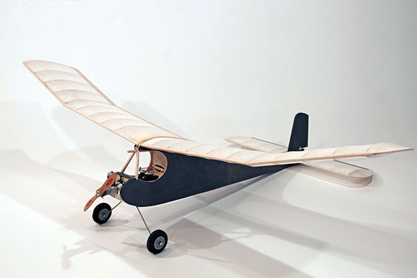
Model type: Kit Skill level: Intermediate Wingspan: 44 inches Length: 30 inches Weight: 11.95 ounces Construction: Wood; Coverite Price: $73.75 Requires: Four-channel radio and receiver; two servosTest-Model Details
Engine: Cox Babe Bee .049 Propeller: 5.5 x 3 Tornado Radio system: Spektrum DX8 transmitter; Spektrum AR400 receiver; two Hitec HS-82MG servos; Thunder Power Pro Lite 380 mAh 2S LiPo receiver battery; Castle Creations CC BEC Ready-to-fly weight: 11.95 ounces Flight duration: 1 minute; 45-second engine runPluses
• Full-size rolled plans. • Color-printed manual. • Parts to mount different power systems are included. • Full hardware package.Minus
• Some discrepancies in the manual.Product Review
How many times have you heard or possibly said, “I just don’t have the time to build?” Without a doubt, ARF/RTF model airplanes have brought this wonderful hobby to those who don’t have the time to devote to building. There is much to be said for being able to open a new ARF box and within a few hours—or perhaps even minutes—being able to head to the flying field. Not every model airplane build needs to take months spent hunched over the workbench. There are a great many kits still available, and exponentially more plans, that can be built, finished, and made ready to fly in a short amount of time. One of these kits is the BMJR Models Super Sniffer, a modernized version of a 1950s Free Flight (FF) model converted to RC. In fact, after only six hours of enjoyable construction time, I was admiring a completed airframe ready for final sanding and covering.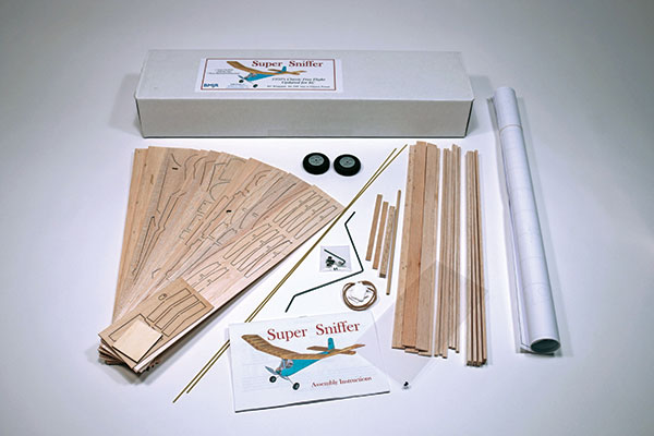
The Super Sniffer is a complete, quality kit at a reasonable price.
It should be noted that I build at a glacial pace because it’s how I relax and I enjoy it too much to hurry it along. Just opening a new kit can offer an hour of delight, if you take the time to read the manual, study the plans, and simply familiarize yourself with the kit and all of its contents. If you still find the task of building a model airplane to be daunting, take the opportunity to enlist the help of a club member who builds. You might be surprised by the lengths a builder will go to in order to share this dwindling aspect of our hobby with a fellow modeler. BMJR’s slogan is, “For modelers that like to build what they fly.” I believe that after you see how easy and enjoyable it is, you will become one of those modelers.
Construction
The included, color-printed manual begins with the assembly of the tail group. The horizontal stabilizer is a built-up assembly of open bay construction, which calls for a simple procedure to ensure a straight-and-true structure. The following should be employed on any wing section of similar construction. Paper plans shrink and expand with fluctuations in humidity so the distance from the leading edge (LE) to the trailing edge (TE) might not match the actual length of the ribs. If the spar is first pinned down on top of the plans, the ribs can be used to place the LEs and TEs. This is where laser-cutting shines. No longer are there ribs of varying lengths to give the builder problems. Right here is where previously taking the time to study the manual, plans (in this case, full-size, rolled plans), and kit contents will pay off because there are a few discrepancies in the manual. The answer to any question that the manual might present is likely on the plans or made clear by the parts themselves. Neither the manual nor the plans are well defined on the 1/16-inch sheeting on the bottom of the horizontal stabilizer, but a little studying will make it clear that the sheeting is inlaid so it is flush with the bottom surface of the stabilizer. This provides a gluing surface for attaching the stabilizer to the fuselage. After the stabilizer was completed, I noticed that the ribs’ TEs were beyond the 3/16-inch square TE by approximately 1/16 inch. At this point, I fired off an email to BMJR to see what I had done wrong. The company explained that they were intentionally left tall to allow the builder to fair the ribs into the TE. After a few minutes with a bar sander, the horizontal stabilizer was finished.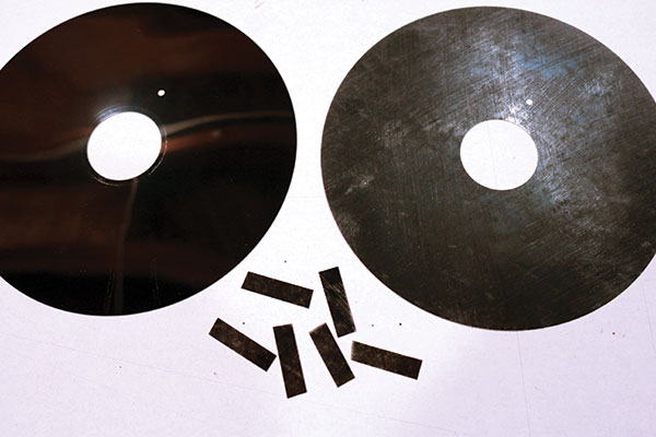
If you can find some old floppy discs, you will have the best lightweight airplane hinge material that the author has ever found.
The vertical fin and rudder are composed of a few pieces of laser-cut sheet stock. The rudder is where I made a minor, but important, modification. As supplied, the rudder is made up of two pieces with the grain running horizontally, which made for a rather flexible rudder. My solution was to remove a 3/16-inch slice from the rudder’s LE and replace it with a strip of vertical-grain balsa. I slotted the tail surfaces for hinges before covering. On models of this size and smaller, I have yet to find a better hinge material than strips cut from floppy discs. They are not glued in until after the surfaces have been covered. The wing is a polyhedral design containing four individual panels. What this means for the builder is three dihedral joints. This is one situation where I consider my miter sander to be indispensable. This simple tool allows a builder to sand the same angle, squarely on all adjoining faces of the spars, LEs, and TEs. A better-fitting joint is always a stronger joint. The procedure is the same as that used for the horizontal stabilizer. Pin down the spar and use the ribs to locate the TE and LE. Here I found another discrepancy in the manual. It suggested shimming only the front of the TE, resulting in a wedge-shaped gap at the rib-to-TE joint. I remedied this by placing the shims under the TE front to rear. Following the manual for the order of construction makes it all straightforward. When all four panels have been completed and removed from the board, the small tabs on the bottom TE of the ribs are removed and the ribs are sanded for a smooth transition into the TE and each panel’s LE is sanded to shape. When joining the panels, it might be necessary to lightly sand the joints to get a nice fit. The key to a straight and true structure is to never spread apart a too-tight joint, and never pull together a too-loose joint. Doing either of these will practically guarantee a built-in warp.
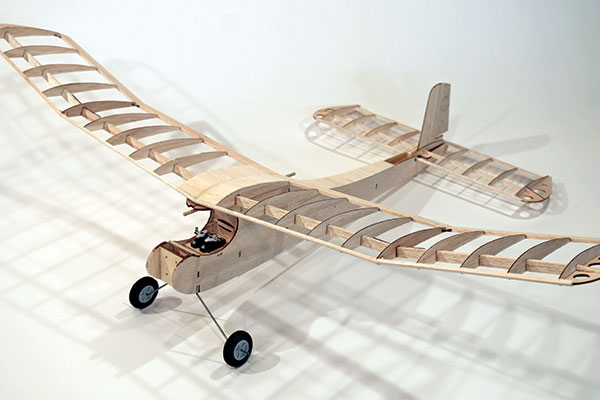
Only a few hours of slow-paced, enjoyable building, and the BMJR Super Sniffer was framed up.
The laser-cut triangular gussets are an important structural component at each dihedral break, so make sure they aren’t omitted. Take the time to sand a V notch into those gussets that are used at the LE to give them as much gluing surface as possible. If, after joining the panels and unpinning them from the board, you find there is a warp in the wing, all is not lost. This style of structure is rather flexible and relies on the covering for a great deal of its torsional rigidity. This means that you can remove all but the worst warps when you cover the wing. The fuselage construction is as straightforward as it gets; however, a few tips will help ensure a straight and true structure. When joining the forward fuselage section to its aft section, I recommend pinning down the forward section on top of the plans. The adjoining laser-cut, V-shaped joint is quite accurate, but will still allow for some misalignment. With the forward section pinned down, you can adjust the alignment of the aft section to follow the plans, ensuring a true fuselage side. After both sides have been glued, but before adding the joint doubler, block sand both fuselage sides inside and out. This provides a true, flat joint on the inside over which to glue the doubler, and a nice smooth outer surface for your chosen method of covering. It’s possibly the most overused warning in modeling, but be sure to make a left and a right fuselage side. When assembling fuselage formers F1, F2, and F3, I suggest the use of some sort of squaring tool(s). My preference is a pair of machinist’s 1-2-3 blocks. These simple blocks are another tool I use in nearly every build. They get their name by being 1 x 2 x 3 inches. By assembling this trio of formers squarely, a true fuselage is much easier to accomplish. At this point, you must decide what will power the Super Sniffer. I used a Cox Babe Bee .049 glow engine because I love that 1/2A wail. Whatever your choice of power, the manual has clear pictures of the different nose configurations.
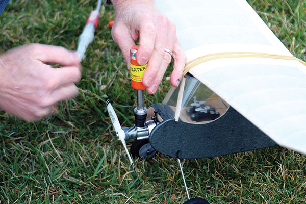
If you don't have a Cox Glow Plug Clip you can easily use a Ni-Starter from Sonic Tronics.
After that step has been completed, the fuselage is ready for the cross-grained sheeting on the top and bottom. Don’t simply grab whatever sheeting is at hand and start gluing it on. Select lighter, softer balsa for the aft section, and heavier, harder wood for the nose area. I sheeted the top section first because this allowed me to pin the fuselage to the top plans view. After it is pinned down, the fuselage sides can be pinched together and glued using a square to ensure that the vertical glue joint is aligned over the centerline. Carefully sheet the top to make sure a bow is not induced by pushing or pulling to one side. With the top of the fuselage sheeted, the assembly can simply lie upside down to sheet the bottom, but care must still be taken to not create a banana-shaped fuselage. With all of the individual components completed, it’s time to give everything a thorough finish sanding. The order of covering and assembling, or assembling and covering, is dictated both by your choice of covering material and personal preference. I chose tissue and dope on the sheet surfaces (fin and fuselage), and Polyspan and dope on the open bay structures (wing and stabilizer). A lightweight iron-on film would have been easier and quicker, but again, I’m in no hurry. I followed the manual to install the engine and radio equipment with no problems. Just make sure the servos and linkages are secured before you glue on the wrap-around windscreen. Had I used electric power, I probably would have installed the ESC in the cockpit area with the servos and perforated the sides of the windscreen to provide cooling air.
All that’s left to do is install the windscreen after the servos are thoroughly checked.
The final all-up weight of my Super Sniffer is 11.95 ounces. It balanced perfectly with no ballast necessary. All that was left to do was wait out the weather.
Flying
Near the end of March, I was blessed with a decent day. The Cox .049 engine had been previously broken in, so I felt comfortable running it with the needle valve set extremely rich. Doing this greatly reduces the rpm, giving it a slower flying speed and allowing for a more relaxed initial trim flight. With the engine blubbering away, the Super Sniffer was given a gentle hand launch into the breeze and it was off on its maiden flight. With no trim changes necessary, I let the airplane gain what altitude it could to give me a taste of the glide when the engine quit. When the engine did quit, the Super Sniffer transitioned seamlessly into a wonderful flat, slow glide. The next flight was undertaken with the Babe Bee running full throttle. The model climbed out with too much authority for only a second flight, so I dialed in three clicks of down-trim. After only 2 minutes or so of engine run, the Super Sniffer was just a speck in the sky. While the engine was still screaming away, the wind aloft brought the airplane to a complete halt (undercambered airfoils aren’t known for their penetrating abilities). A shallow dive brought it back upwind with enough altitude left to enjoy watching a classic shape float around in lazy circles. As I write this, summer is on the way, and with it comes afternoon thermals. I’ll be ready with my BMJR Super Sniffer, a quart of Sig 1/2A fuel, and a lawn chair because I know this airplane is going to be up there for some long flights. Blue skies. —Dan Gaston [email protected]Manufacturer/Distributor:
BMJR Models (321) 537-1159 www.bmjrmodels.comSources:
Horizon Hobby (800) 338-4639 www.horizonhobby.com Hitec RCD (858) 748-6948 www.hitecrcd.com Castle Creations (913) 390-6939 www.castlecreations.com Thunder Power (702) 228-8883 www.thunderpowerrc.comThis Month's Issue

Join the AMA
![]()


Add new comment