


Dornier Do R 4 Super-Wal
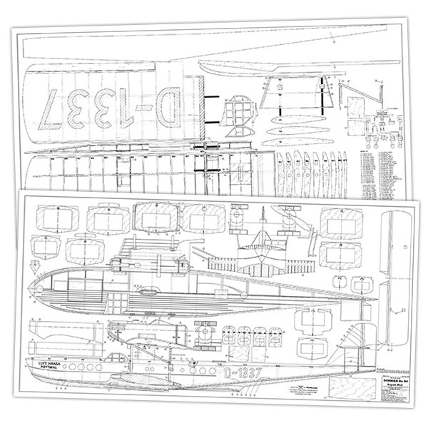
Laddie Mikulasko’s Dornier Do R 4 Super-Wal Build the multiengine, record-setting seaplane. Article, plans, instructions, and photos by Laddie Mikulasko. Complete build instructions and additional construction photos from the April 2014 issue of Model Aviation.
In 1914, Claudius Dornier established a company called Dornier Flugzeugwerke. Throughout its long history, the company produced many innovative designs for the civil and military markets. Until the beginning of World War II, Dornier concentrated on producing seaplanes. The most successful design was a two-engine Do J Wal. The Wal was a popular airplane and approximately 300 were produced. European and South American airline companies used a large number of Wals. In addition to the two-engine Wals, Dornier also built 19 four-engine R 4 Super-Wals that could carry up to 19 passengers. My model is built from foam boards that I purchased at the dollar store. The model is powered by four Turnigy 3536/9 motors. The front motors are powered by a 3S 3,000 mAh battery turning the 9 x 6 propellers at 15 amps each. The rear motors have a 3S 3,000 mAh battery and are turning the 9 x 4.5 propellers at 12 amps each. The model could be flown using one 3S 6,000 mAh battery, but it needs added weight for balancing, so I used two batteries. I redrew the plans to use foam instead of balsa. I made the wing in three sections for easier assembly and disassembly.
Building the Model
The first step is to remove the paper from the 3/16-inch-thick foam boards. Save the paper because you will need it for finishing. Because the fuselage sides and the horizontal tail surfaces are 3/8-inch thick, the sheets must be glued together on top of each other to achieve the proper thickness, then glued end-to-end to make two 70-inch-long strips. Spray contact cement glue onto one side of each strip. Glue the strips to each other, but make sure that the dividing lines between the sheets are approximately 2 inches apart. Build the tail surfaces first. The fin and the rudder are made by gluing three sheets of foam together to achieve 9/16-inch thickness. Cut out the fin (20) and the rudder (22) from this sheet. Glue the hinge spar (21) to the fin (20) and the LE spar (23) to the rudder (22). Cut out the stabilizer (24) and the elevator surfaces (26) from a 3/8-inch-thick foam sheet. Glue the hinge spar (25) to the stabilizer (24), and the LE spar (27) to the elevators (26). Sand all of the surfaces to the shapes as shown on the plans. Cut out the opening for the stabilizer in the fin. On the right side of the fin, make the channels for the elevator and the rudder flexible tubing. Glue in the tubing. At the bottom of the stabilizer, in the locations shown, glue in the 1/4-inch balsa blocks (29) to hold the stabilizer support struts (44).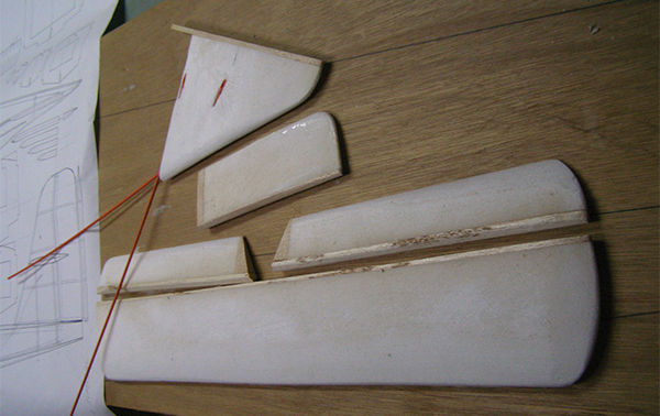
The tail surfaces are 3/8-inch thick. Two 3/16-inch foam sheets are glued together and then sanded to shape.
Building the Wing
Cut out all of the ribs. It is important to accurately drill the holes for the carbon-fiber tubes. The wing is built in three sections. Begin building the outer wing panels first. Because the individual sheets are only 30 inches long and the bottom wing sheet needs to be slightly longer, glue on a 2-inch strip to get the 32-inch-long sheet. Transfer the shape of the outer wing panel onto the bottom sheet (56). Cut out the shape of the outer panel from this sheet. Transfer the location of the spars and the ribs onto the sheet. Glue the bottom main spar (52) and rear spar (53) to the sheet. Position and glue ribs W4 to W9 to the spars and to the sheet. Glue the top spars (52) and (53) to the ribs. Between the W4 ribs, glue in the plywood sheer web to the ribs and to the spars. Cut the carbon-fiber tubes to the proper length and glue them to the W4 ribs and to the plywood web. Put this wing panel aside. Build the other wing panel to the same stage, and when it is complete, begin building the center wing section. Transfer the location of the spars and the ribs onto the bottom foam sheet (56). Glue the bottom main spar (52) and rear spar (53) to the sheet. In the center of the wing, glue the plywood plates (54) to the bottom sheet and to the main spar. Glue ribs W1 and W2 to the spars and to the bottom sheet. Glue the top main and rear spars to the ribs. Between the W2 ribs, glue the 1/8-inch-thick plywood sheer web to the ribs and to the main and rear spars. Plug the outer wing panels into the center panel to check the alignment. Flip the wing panels on their backs and cut out the openings in the bottom sheeting at ribs W2 and W6 for the 1/4-inch plywood blocks (60) and (65). Glue the blocks to the ribs and to the bottom sheeting (56). The blocks (65) will hold the plastic or the aluminium clip that holds the outer wing panels to the center panel. Glue the top sheeting (57) to the ribs and to the center section spars. Glue the two foam strips (58) to the center section LE. In the rear of the center section, glue the TE (59) to the top and bottom sheeting. Before gluing the top sheeting to the outer wing panels, sand the TE so that it tapers to nothing, as shown on the plans. Pull in the aileron servo extension wires from the F4 to F6 ribs. The top sheeting of the other wing panel is in two halves—one is from the rib F4 to the last F5 rib, and the other is from the F5 rib to the wingtip. Glue the top sheeting to all the ribs and spars between F4 to the last F5 rib. After that, glue the top sheeting from the F5 rib to the wingtip. Glue two strips of foam (58) to the LE and glue the aileron hinge spar (61) to the TE. Sand the wing panels. Glue ribs W3 to ribs W2 and to ribs W4. Flip the wing panels on their backs. Drill 1/8-inch holes in the plywood blocks (60) between ribs W2 for the cabane struts and drill 3/32-inch holes into the plywood blocks between the W6 ribs for the screws, which will hold the wing struts. From a 1/4-inch-thick balsa sheet, cut out the ailerons. Cut out the opening for the aileron servo. Sand the wing panels and put them aside.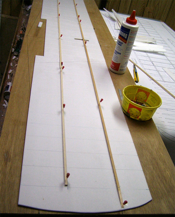
The spars are glued to the wing’s bottom skin. For easy alignment, the location of each rib is marked on the skin.
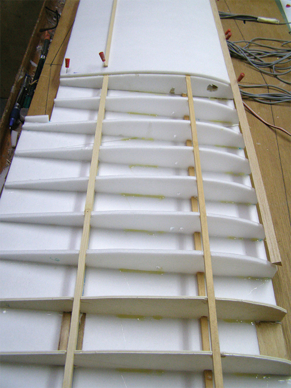
The ribs have been glued in place and top spars glued to the ribs. The top sheeting is being glued on.
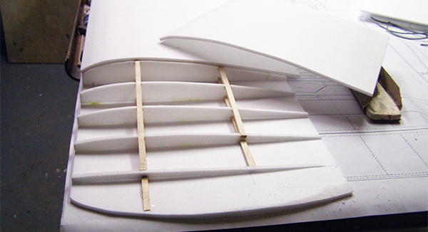
This shows the sheeting nearly completed. The wingtip section is ready to be glued on.
Building the Fuselage
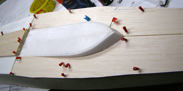
Transfer the shape of the hull side onto 3/8-inch foam sheets. (The actual shape of the side is shown at the top of the plans drawing number 2.) Cut out the hull sides (16). Glue the plywood doubler (7) to each hull side (16) in the location shown on the plans. Cut out all of the plywood and foam bulkheads. Notice that most of the bulkheads have tabs at the top. Cut them out and then reattach them with masking tape. These tabs keep the bulkheads at the right height when building the hull upside down. Pin the bulkheads upside down to the building board. Glue in the front keel (1) and rear keel (2) to the formers. Glue the top (3) and bottom (4) longerons to the bulkheads. Each front longeron—from former F1 to former F5—is cut lengthwise in the middle, so they are easy to bend when you are gluing them to the formers. Glue the hull sides to the bulkheads. Sand the longerons so that they follow the bulkheads’ contour. Glue the hull bottom sheets (8) and (9) to the hull sides and to the bulkheads. Behind the bulkhead F8, make a secondary step by gluing the step sides (10) to bulkheads F9 and F10 and to the bottom sheeting (9). Glue the bottom foam sheeting (11) to the sides (10). Make the bottom of the hull dent resistant by using contact cement to glue balsa sheets (12) and (13) to the hull bottom. Flip the hull right side up and remove the tabs from the bulkheads. Glue the battery floor (67) to bulkheads F2 to F6. Where bulkhead F10 is located, glue in the mounting beams for the elevator and the rudder servos. Glue in the top longeron (14) to all of the formers. Take the fin (20) and feed the flexible tubing for the elevator and the rudder through the holes in bulkheads F12 to F7. Glue the fin to the hull. Glue the top foam sheeting (15) to the hull sides and to all of the formers. Glue the balsa nose block (16) to former F1. At formers F6 and F8, cut out the foam in the hull sides all the way to the doublers. Glue in two hardwood blocks (30) to the doubler (7). In the hardwood blocks (30), drill the holes for the cabane wire struts and sand the hull. Between bulkheads F3 and F5, cut a large opening for the removable hatch. In the rear, where the two servo mounting beams are located, also cut an opening for the servo access hatch. Make the wing center pylon. Glue the plywood sides (18) to the 1/4 x 3/8-inch balsa blocks. Glue the balsa sheets (17) to the plywood sides. Glue the LE (19) to the pylon, then sand to shape as shown on the plans.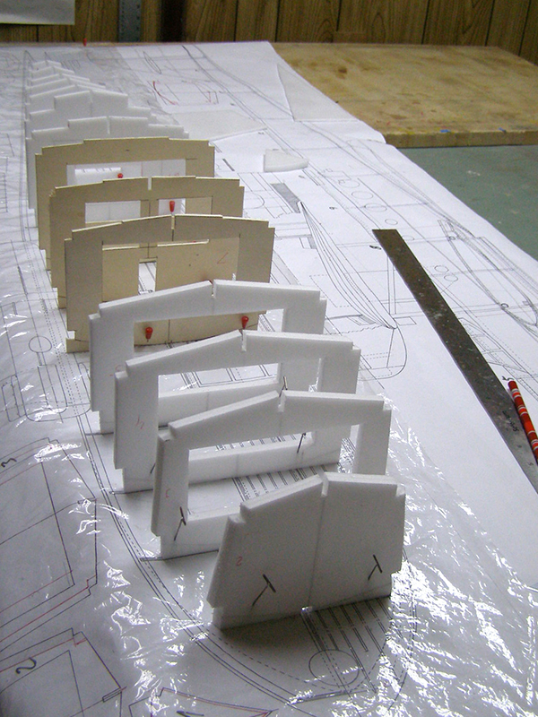
The plywood doublers are glued to the hull sides and the fuselage bulkheads are positioned and pinned to the building board. Notice that the tabs are attached to the bulkheads.
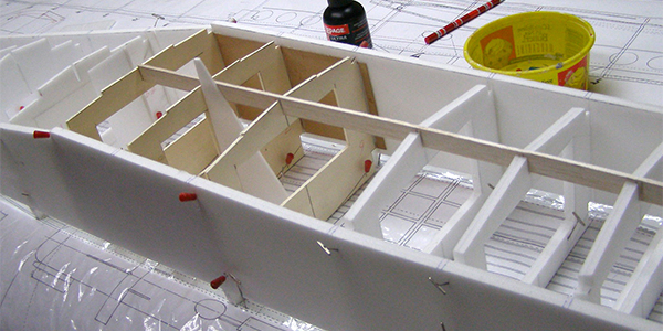
The hull sides are glued to the bulkheads. The longerons will be added next.
The longerons are glued in. Each front longeron is split in half so in can easily be bent. The battery floor is also glued to the bulkheads.
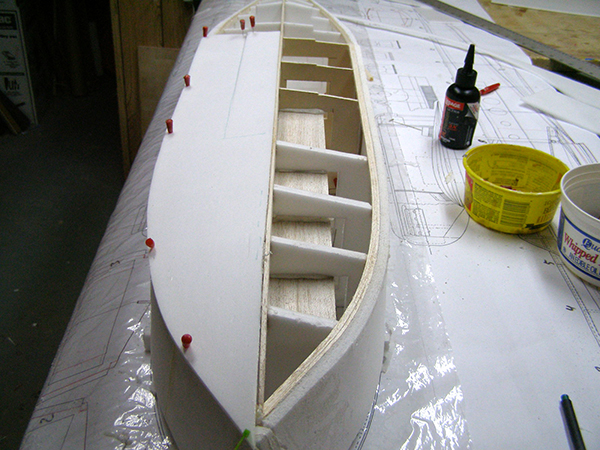
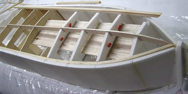
Here the bottom sheeting is being glued to the bulkheads.
The entire bottom of the hull is covered with 1/16 balsa sheets.
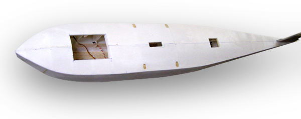
The hull is taking shape. Next the author will cover it with paper and add scale detailing.
Building the Sponsons
Cut 1/4-diameter carbon-fiber tubes (47) to the proper length as shown on the plans. Slide the tubes into S1, S2, and S3 and then glue them to the ribs as shown on the plans. Place two shims of the same height under the tubes while the glue dries. Glue the TE (46) to the ribs. While the shims are in place, glue the top sheeting (50) to the ribs and to the TE. When the glue is dry, flip the sponsons over and glue the bottom sheeting (49) to the ribs. Glue the LE (51) to the sponsons. Cap the end of the S3 rib with 1/8-inch balsa sheet (63). In the location shown on the plans, cut an opening in the top sheeting and glue in the plywood blocks (48). Sand the sponsons and then put them aside.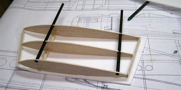
The sponsons are reinforced with 1/4-inch diameter carbon-fiber tubes.
The Cockpit
Cut out all cockpit sides. Using thick CA, glue the sides to the crossmembers to form the cockpit and then glue on the cockpit top. Brush the sealer onto the frame and after it’s dry, sand the cockpit frame.Building the Nacelles
Cut out plywood formers N1 to N4 and glue the magnets to them. Check the polarity to ensure that the former N1 is attracted to the N2, and N3 to N4. Next, glue in the guide dowels to formers N1 and N4. Using a 3/8-inch foam sheet, cut out the nacelle sides (33). Glue the former N2 to the front of the nacelle and the former N3 to the rear of the nacelle and then glue the sheet (36) to the top of the nacelle. In the front, bottom part of the nacelle, glue the sheets (39) to the N2 former and to the nacelle sides (33). Glue the sides (34) of the front cowl to the N1 former. Glue the top sheet (37) to the N1 former and to the cowl sides. Glue the sides (35) of the rear cowl to the N4 former. Glue the top sheet (38) to the cowl sides and to the N4 former. At the back of the cowl, glue a 3/8-inch foam sheet (40) to the sides. Plug the cowls into the nacelle and sand to shape as shown on the plans. The model’s bare foam can be covered with the paper that was removed from the foam boards, or with brown packing paper. The fin, the rudder, the stabilizer, and the elevator surfaces can be covered with lightweight Japanese paper or Modelspan tissue paper. Use carpenter’s glue that has been diluted to approximately 60% glue and 40% water to adhere the paper to the surface. You can also use a water-based clear polyurethane sealer, but don’t dilute it. Before the covering is applied, brush one coat of the sealer on the entire model. After the sealer is dry, sand the seaplane with 60- or 80-grit sandpaper. If there are dents or other surface damage, fill them with the water-based filler and then sand some more. Cover the center section of the wing first so you can practice covering with the paper. Cut out two sheets of the brown or white paper large enough to overlap the center section of the wing by 1 inch on all sides. Flip the wing onto its back and brush on the sealer or diluted carpenter’s glue. Spray the paper with water until damp. Use a cloth to remove excess water. Place the damp paper onto the bottom of the wing and brush on a light coat of the sealer on the paper. Use a squeegee to smooth the paper and push out most, but not all, of the sealer, because the sealer acts as glue. Wrap the overhanging paper over the LE and TE. When the bottom is covered, immediately brush the sealer onto the top surface of the center section of the wing and place a damp paper sheet on it. Brush some sealer on the paper, smooth it with a squeegee, and wrap excess over the LE and TE. Always overlap adjoining sheets of paper. While the paper is wet, locate the holes for the cabane struts and puncture them. If you don’t do this, it will be difficult to locate them after the paper dries. Anytime you cover thin surfaces with paper, such as the wing and tail, cover the top and bottom surfaces at the same time. While the paper is wet, place the surfaces vertically—allowing them to air dry. Otherwise, the surfaces will warp. Cover the outer wing panels. Do not attempt to cover the entire wing surface in one step. Because it is a large area, if you tried to cover the entire wing with one sheet, the paper would bunch when you used the squeegee to remove excess glue. Cut the paper so that one sheet covers only one half of the one wing panel. Cover the bottom and then the top. When you are finished covering the top and bottom of that half of the wing panel, let the paper dry. Locate the holes for the wing struts and puncture them. While the paper is drying, cover the other panel. To cover the wingtip edges, make cuts in the paper 1/2 inch apart so it easily forms around the wingtips. Cover the tail surfaces with thin paper such as Modelspan. Use brown paper to first cover the hull sides then the top and bottom of the hull. While the paper is wet, puncture holes for the cabane struts in the hardwood blocks (30) and the holes in the balsa blocks (28) for the stabilizer struts (44). Cover the sponsons. Before the paper dries, make sure that you punctured the holes in the plywood blocks (48), then cover the nacelles. Lightly sand every part that was covered with paper and try not to go into the paper or the foam. If that happens, cover that spot with a patch of paper. When you’ve completed sanding, brush on another coat of sealer. Some areas may need lightweight filler. When the filler dries, sand it to prepare it for painting. Brush on one more coat of sealer on all surfaces. Glue the center pylon to the top of the hull and the F7 bulkhead. Glue the stabilizer to the fin, smear epoxy glue onto the sponsons’ S1 rib and the carbon-fiber tubes, and then glue them to the hull sides and to the F6 and F8 bulkheads. Glue the cockpit to the hull, and then glue the nacelles to the wing. Ensure that the motor wires are pulled into the nacelles and out of the N2 and N3 formers.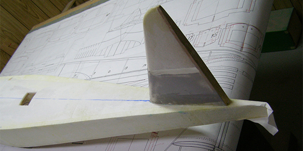
The hull is covered with paper. You can use the paper that was removed from the foam boards or brown packing paper.
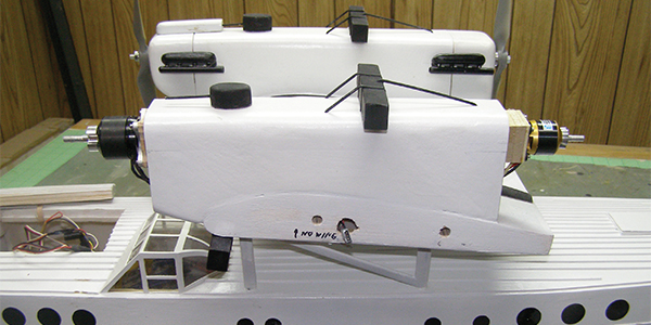
The model is powered by two 2820/14 motors in the front of the nacelles and by two 2212/34 motors in the rear of the nacelles.
Make the Cabane
First, make the four cabane struts—two for the front (31) and two for the rear (32). Bend them to the shape as shown on the first plans page. Take the electrical lugs and bend the eye to roughly 90°. Slide the electrical lugs onto each strut and insert each strut into the holes in the hardwood blocks (30). Using scrap pieces of foam sheets, cut out a V-shape cradle so that the hull can securely set in it at a 90° angle to the building board. Plug the wing panels into the center section. Slide the wing onto the fuselage pylon. At the same time, guide the cabane wires into the holes in the bottom of the wing. Ensure that the wing is perpendicular to the hull at a positive angle of attack as shown on the plans. If the holes are slightly misaligned, rebend the strut’s wires. When the wing is aligned, slide the electrical lug until it touches the plywood block (60) on the bottom of the wing. Make sure that the eye is positioned over the hole for the screw that will hold the wing to the fuselage. Use pliers to crimp the lug onto the cabane strut. Do the same for other three. When done, gently remove the wing. Take each strut and solder the lug to the wire. When the soldering is done, insert each strut back into the hardwood blocks (30). Place the wing back onto the pylon and onto the cabane struts. Cut out two plywood cabane frames (41) and insert them between the struts (31) and (32). Glue them to the struts with epoxy. After the glue hardens, remove the wing and remove the cabane from the hull. Wrap fiberglass cloth around the wire struts and the plywood frame. Saturate the cloth with CA glue and then sand the cabane. At the bottom of the cabane, smear epoxy glue onto the wires. Insert the cabane wires into the holes in the blocks (31). Place the wing back onto the top of the cabane and the fuselage pylon. Make sure that the wing is still aligned and let the epoxy cure. After the glue has hardened, use four screws to attach the wing to the cabane.Make the Wing Struts
The simplest way to make the struts is to use K&S Streamline Aluminium Tubes. Cut them to the required length, flatten both ends of the struts, and bend the ends of the tubing so that the flat part of the strut is flush with the wing at one end and with the sponsons on the other end. Drill the holes in the flat part of the strut. Mount the wing struts to the wing and to the sponsons. Watch for wing warping. In the rear of the hull, glue the struts between the stabilizer and the hull. There is one more thing to do to give this model a scalelike look. As the plans show, the hull and the sponsons have antislip corrugated strips on the top surfaces of the fuselage and sponsons. To simulate corrugation, cut the 1/16 balsa sheet into 1/16 x 1/16-inch strips. Some of them will not be long enough so you will have to splice them. Before gluing in place, take each strip and lightly sand it with 100-grit sandpaper. Seal the balsa with dope or polyurethane sealer and sand again. Using the plans drawing as a reference, glue the balsa strips to the hull and to the sponsons.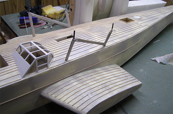
The cabane strut has been glued to the hull. Notice the electrical lugs soldered to the cabane wires.
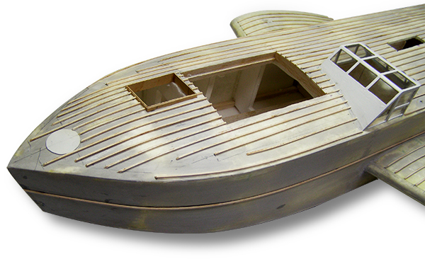
The hull and the sponsons have antislip corrugated strips on the top of their surfaces to add scalelike detailing.
Painting and Finishing
Use your favorite paint. The seaplane is white except for the bottom of the hull, the top and bottom of the sponsons, the wing struts, and the black registration numbers. Use scrap balsa to make the dummy engine heads and the radiators, and paint them black. Glue the engine heads to the cowls. Inside the cockpit frame, glue in the windows. Install all of the hinges, horns, servos, and pushrods. Solder the connectors to the motor wires. Solder the servo plugs onto the elevator, rudder, and the aileron extension wires. Install the motors. Because the rear motors are smaller, make and glue the false firewall to the N3 formers. Connect all of the electrics as shown on the schematic located on the second plans page. Notice that the three speed controllers have the red wire lifted. If this is not done, the speed controllers will not properly work. Install the batteries and position them so that the model balances on the CG point as shown on the plans. To have differential control of the rear motors, you need to install a V-tail mixer as shown on the schematic. Check the differential motor control by moving the rudder stick to the left. The rudder should move left and the rear right motor should speed up. The opposite will happen when moving the stick to the right.Flying
Takeoffs are smooth, and the model is a gentle flier. Good luck.—Laddie Mikulasko [email protected]
Order Plans


 |  |
List of Supplies
Thirteen 20 x 30 x 3/16 (4.5mm to 5mm) foam boards Foam-safe glue Eight 1/8 x 1/4 x 36 spruce spars One 1/32 x 12 x 6 plywood sheet One 1/8 x 12 x 12 plywood sheet One 1/16 x 12 x 12 plywood sheet One 1/4 x 6 x 6 plywood sheet One 1/4 x 36 x 3 balsa sheet Six 1/16 x 36 x 3 balsa sheets One 1/8 x 36 piano wire Water-based clear Polyurethane sealer 3M 77 contact cement spray 40- and 60-grit sandpaper See the plans for more supply details.Specifications
Type: Semiscale amphibian Skill level: Intermediate Wingspan: 72 inches Length: 62 inches Weight: 9.5 pounds Wing loading: 23 ounces per square foot Construction: Foam, balsa, and plywood Finish: PaintedSOURCES:
K&S Precision Metals (773) 586-8503 www.ksmetals.com AMA Plans Service (765) 287-1256, ext. 507 www.modelaircraft.org/plans.aspxThis Month's Issue
Join the AMA
![]()


8 comments
What glue did you use for general construction
Glue used
Glue
Paint
Paint
Dornier motors
any will work
This is a great article but I
Add new comment